
2N2222A Transistor

For the design of the circuits testing the saturated turn-on and turn-off times of the 2N2222 transistor, careful consideration of component selection and configuration is essential to obtain accurate measurements. The first circuit's output, taken from the collector, is essential for monitoring the turn-on characteristics. A pull-up resistor connected to Vcc ensures that the collector voltage is high when the transistor is off. The second circuit, utilizing a resistor divider for output, allows for a more controlled measurement of the turn-off time.
The bias voltage adjustments between the two circuits must be precise to ensure accurate comparisons of the turn-on and turn-off characteristics. The maximum collector-to-emitter voltage rating of 40 volts indicates that the circuit should be designed with adequate voltage ratings for all components to avoid breakdown.
Non-inductive resistors are crucial in both circuits to minimize parasitic inductance, which can distort the rise and fall times of the output signal. The specified rise time of 2.0 ns and the generator's source impedance of 50 Ohms are critical parameters to maintain signal integrity, especially when interfacing with the sampling oscilloscope.
The oscilloscope's specifications, including an input impedance of 100 kΩ and a capacitance of 12 pF, are important for ensuring minimal loading on the circuit under test. The rise time of the oscilloscope, set at 5 ns, should be considered when interpreting the output waveform, which may appear rounded due to the saturation effect of the transistor.
The T-on time measurement is vital for understanding the switching characteristics of the transistor, and attention must be given to the pulse width and its relationship with the rise and fall times. The design should ensure that the pulse width remains at 200 ns while keeping the input rise time within the specified limits.
In conclusion, this testing setup for the 2N2222 transistor is designed to provide reliable and accurate measurements of its saturated turn-on and turn-off times, which are critical for evaluating the performance of the transistor in various applications. The use of common components like the 2N2222A and 1N916 ensures availability and ease of replication for further testing and experimentation.The first circuit, shown below, tests saturated turn-on time, while the second circuit tests saturated turn-off time for a 2N2222 transistor. Note that the first circuit schematic takes the output from the collector, which is pulled high to Vcc.
While the second schematic takes its output from a resistor divider circuit. Also note that the bias vo ltage changes between the two schematics. The maximum Collector-to-Emitter voltage is 40 volts, but the circuit voltages uses 30 volts. Although there is no note in the schematic, use non-inductive resistors so the rise and fall times are not effected but the inductance of the resistors. The rise time (tr) of the applied pulse shall be = 2. 0 ns, duty cycle = 2 percent, and the generator source impedance shall be 50 Ohm. Sampling oscilloscope: ZIN = 100 k ohm, CIN = 12 pF, rise time = 5 ns. The output waveform is `rounded` because the transistor is in saturated. When a transistor is in saturated it takes longer for it to come out of saturation or switch. So a pulse edge applied to a transistor in saturation is slowed on the output, in this case inverted as well.
The T-on time is the value being measured with this circuit. The pulse width is shortened or degraded as the rise and fall time is increased and invades the pulse width time. For a 2N2222 the input rise time should be set at less than or equal to 2nS. The pulse width is of less importance but remains as shown at 200nS. Note that although no power supply by-pass capacitors are shown, filtering capacitors should be used to filter noise from the supply during the test.
Although the package type is of little importance for this test, the derating curves for the 2N2222 use a TO-18 Metal Can. The test circuit is some what generic, so basically any transistor could use the circuit set-up [using the correct Vcc].
Both the 2N2222A transistor and the 1N916 diode are in full production and available for purchase. The 2N2222 is a very common NPN general purpose transistor which has been in service for many years. The 1N916 is also a very common small signal diode in a DO-35 package. 🔗 External reference
Related Circuits
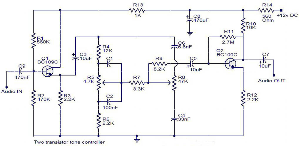
The electrical schematic diagram presented below illustrates a simple two-transistor tone controller audio circuit, which is available for free download. This circuit is based on the well-known Baxandall tone control design. Variations in the values of the transistor components...
The first BC109C transistor functions as a buffer, offering the circuit an input impedance of approximately 250,000 ohms and a voltage gain just below unity. As the Baxandall tone control circuit is a passive design, it attenuates all audio...
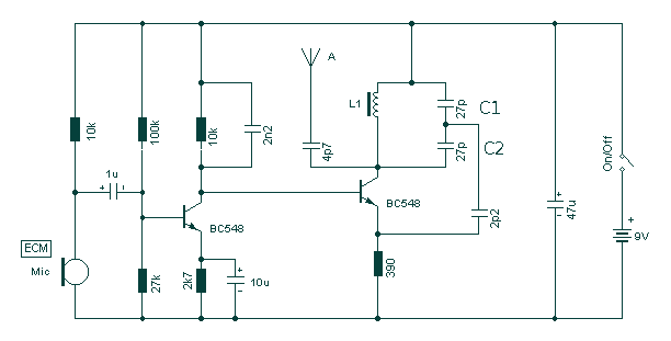
Take care with transmitter circuits. It is illegal in most countries to operate radio transmitters without a license. Although only low power this circuit may be tuned to operate over the range 87-108MHz with a range of 20 or...
This circuit is a single transistor flyback (Joule Thief) circuit that features a third coil. With it, flash duration and brightness are significantly enhanced. The single transistor flyback circuit, commonly known as a Joule Thief, is designed to efficiently convert...
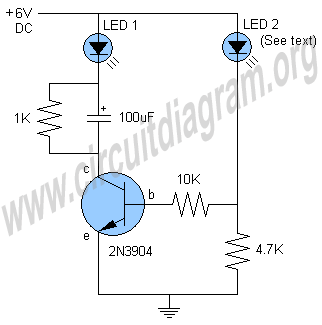
This is a one-transistor LED flasher circuit designed to flash a super bright LED. The circuit employs a single transistor as a driver, which receives the flash rate from LED 2, a self-flashing LED. The flash rate can be...
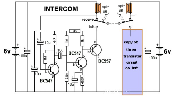
The key to avoiding instability (motor-boating) in a high-gain circuit is to power the speaker using a separate power supply. This circuit design allows for the connection of one or two additional stations. It is recommended to construct the...
Warning: include(partials/cookie-banner.php): Failed to open stream: Permission denied in /var/www/html/nextgr/view-circuit.php on line 713
Warning: include(): Failed opening 'partials/cookie-banner.php' for inclusion (include_path='.:/usr/share/php') in /var/www/html/nextgr/view-circuit.php on line 713