
3-5Volt FM transmitter circuit use two BC547
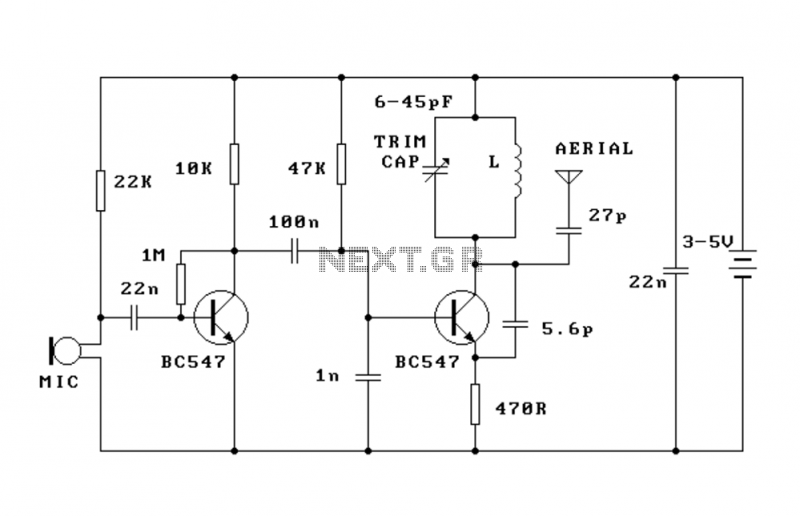
CIRCUIT DESCRIPTION The circuit is basically a radio frequency (RF) oscillator that operates around 100 MHz. Audio picked up and amplified by the electret microphone is fed into the audio amplifier stage built around the first transistor. Output from the collector is fed into the base of the second transistor where it modulates the resonant frequency of the tank circuit (the 5 turn coil and the trimcap) by varying the junction capacitance of the transistor. Junction capacitance is a function of the potential difference applied to the base of the transistor. The tank circuit is connected in a Colpitts oscillator circuit. Let us look at the individual blocks of the circuit more closely: The electret microphone: an electret is a permanently charged dielectric. It is made by heating a ceramic material, placing it in a magnetic field then allowing it to cool while still in the magnetic field. It is the electrostatic equivalent of a permanent magnet. In the electret microphone a slice of this material is used as part of the dielectric of a capacitor in which the diaphram of the microphone forms one plate. Sound pressure moves one of its plates. The movement of the plate changes the capacitance. The electret capacitor is connected to an FET amplifier. These microphones are small, have excellent sensitivity, a wide frequency response and a very low cost. First amplification stage: this is a standard self-biasing common emitter amplifier. The 22nF capacitor isolates the microphone from the base voltage of the transistor and only allows alternating current (AC) signals to pass. The tank (LC) circuit: every Tx needs an oscillator to generate the radio Frequency (RF) carrier waves. The tank (LC) circuit, the BC547 and the feedback 5pF capacitor are the oscillator in the Cadre. An input signal is not needed to sustain the oscillation. The feedback signal makes the base-emitter current of the transistor vary at the resonant frequency. This causes the emitter-collector current to vary at the same frequency. This signal fed to the aerial and radiated as radio waves. The 27pF coupling capacitor on the aerial is to minimise the effect of the aerial capacitance on the LC circuit. The name 'tank' circuit comes from the ability of the LC circuit to store energy for oscillations. In a pure LC circuit (one with no resistance) energy cannot be lost. (In an AC network only the resistive elements will dissipate electrical energy. The purely reactive elements, the C and the L simply store energy to be returned to the system later.) Note that the tank circuit does not oscillate just by having a DC potential put across it. Positive feedback must be provided. (Look up Hartley and Colpitts oscillators in a reference book for more details.)
CIRCUIT CALIBRATION Place the transmitter about 10 feet from a FM radio. Set the radio to somewhere about 89 - 90 MHz. Walk back to the Fm Tx and turn it on. Spread the winding of the coil apart by approximately 1mm from each other. No coil winding should be touching another winding. Use a small screw driver to tune the trim cap. Remove the screwdriver from the trim screw after every adjustment so the LC circuit is not affected by stray capacitance. Or use a plastic screwdriver. If you have difficulty finding the transmitting frequency then have a second person tune up and down the FM dial after every adjustment.
COMPONENTS Resistors (carbon, 0.25W, 5%): 1M (brown, black, green 1 47K yellow, violet, orange 1 22K red, red, orange 1 10K brown, black, orange 1 470R yellow, violet, brown 1 Capacitors: 1n ceramic 102 1 5p6 ceramic 1 22n (223) ceramic 2 27p ceramic 1 100n monoblock 1 BC547, 548 2 5 turn coil 1 Electret microphone 1 Trimcap yellow (6-45pF) 1 Aerial wire 165cm Kit PCB 1 2 AA battery holder 1
The FM transmitter circuit operates fundamentally as a simple radio frequency oscillator, functioning primarily in the FM band around 100 MHz. The design incorporates an electret microphone, which captures audio signals and converts them into electrical signals. This initial audio signal is amplified through a common emitter amplifier configuration using a transistor. The amplified audio is then used to modulate the frequency of the oscillator circuit, which is configured as a Colpitts oscillator using an LC tank circuit consisting of a coil and a variable capacitor (trimcap).
The modulation process occurs when the audio signal alters the base-emitter voltage of the second transistor, thereby changing its junction capacitance. This modulation shifts the resonant frequency of the tank circuit, allowing the transmitted signal to carry the audio information. The resulting RF signal is coupled to an antenna, which radiates the signal as electromagnetic waves.
Calibration of the transmitter is essential for optimal operation. This involves adjusting the coil and trimcap while monitoring a nearby FM radio set to the desired frequency range. The circuit design ensures minimal interference from the antenna capacitance on the oscillator's performance, making it efficient for short-range transmission applications. The overall design is compact, utilizing a single-sided PCB for ease of assembly and integration. The component selection, including resistors and capacitors, is standard and readily available, facilitating the construction of this basic yet effective FM transmitter.This FM transmitter (FM Tx) is about the simplest and most basic FM Tx it is possible to build and have a useful transmitting range. It is surprisingly powerful despite its small component count and 3V operating voltage. It will easily penetrate over three floors of an apartment building and go over 300 meters in the open air.
The circuit we use is based on a proven Australian design. It may be tuned anywhere in the FM band. Or it may be tuned outside the commercial M band for greater privacy. (Of course this means you must modify your FM radio to be able to receive the transmission or have a broad-band FM receiver.) The output power of this FM Tx is below the legal limits of many countries (eg, USA and Australia). However, some countries may ban ALL wireless transmissions without a licence. It is the responsibility of the purchaser to check the legal requirements for the operation of this kit and to obey them.
The kit is constructed on a single-sided printed circuit board (PCB). Protel Autotrax was used to design the board.
CIRCUIT DESCRIPTION The circuit is basically a radio frequency (RF) oscillator that operates around 100 MHz. Audio picked up and amplified by the electret microphone is fed into the audio amplifier stage built around the first transistor.
Output from the collector is fed into the base of the second transistor where it modulates the resonant frequency of the tank circuit (the 5 turn coil and the trimcap) by varying the junction capacitance of the transistor. Junction capacitance is a function of the potential difference applied to the base of the transistor.
The tank circuit is connected in a Colpitts oscillator circuit. Let us look at the individual blocks of the circuit more closely: The electret microphone: an electret is a permanently charged dielectric. It is made by heating a ceramic material, placing it in a magnetic field then allowing it to cool while still in the magnetic field.
It is the electrostatic equivalent of a permanent magnet. In the electret microphone a slice of this material is used as part of the dielectric of a capacitor in which the diaphram of the microphone forms one plate. Sound pressure moves one of its plates. The movement of the plate changes the capacitance. The electret capacitor is connected to an FET amplifier. These microphones are small, have excellent sensitivity, a wide frequency response and a very low cost.
First amplification stage: this is a standard self-biasing common emitter amplifier. The 22nF capacitor isolates the microphone from the base voltage of the transistor and only allows alternating current (AC) signals to pass. The tank (LC) circuit: every Tx needs an oscillator to generate the radio Frequency (RF) carrier waves.
The tank (LC) circuit, the BC547 and the feedback 5pF capacitor are the oscillator in the Cadre. An input signal is not needed to sustain the oscillation. The feedback signal makes the base-emitter current of the transistor vary at the resonant frequency. This causes the emitter-collector current to vary at the same frequency. This signal fed to the aerial and radiated as radio waves. The 27pF coupling capacitor on the aerial is to minimise the effect of the aerial capacitance on the LC circuit. The name 'tank' circuit comes from the ability of the LC circuit to store energy for oscillations.
In a pure LC circuit (one with no resistance) energy cannot be lost. (In an AC network only the resistive elements will dissipate electrical energy. The purely reactive elements, the C and the L simply store energy to be returned to the system later.) Note that the tank circuit does not oscillate just by having a DC potential put across it. Positive feedback must be provided. (Look up Hartley and Colpitts oscillators in a reference book for more details.) CIRCUIT CALIBRATION Place the transmitter about 10 feet from a FM radio.
Set the radio to somewhere about 89 - 90 MHz. Walk back to the Fm Tx and turn it on. Spread the winding of the coil apart by approximately 1mm from each other. No coil winding should be touching another winding. Use a small screw driver to tune the trim cap. Remove the screwdriver from the trim screw after every adjustment so the LC circuit is not affected by stray capicitance. Or use a plastic screwdriver. If you have difficulty finding the transmitting frequency then have a second person tune up and down the FM dial after every adjustment.
COMPONENTS Resistors (carbon, 0.25W, 5%): 1M (brown, black, green 1 47K yellow, violet, orange 1 22K red, red, orange 1 10K brown, black, orange 1 470R yellow, violet, brown 1 Capacitors: 1n ceramic 102 1 5p6 ceramic 1 22n (223) ceramic 2 27p ceramic 1 100n monoblock 1 BC547, 548 2 5 turn coil 1 Electret microphone 1 Trimcap yellow (6-45pF) 1 Aerial wire 165cm Kit PCB 1 2 AA battery holder 1
Related Circuits
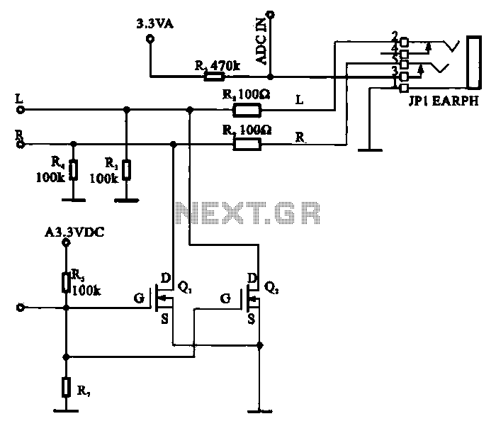
A field-effect transistor (FET) is utilized in a headphone circuit designed to function as a silencer tube. The circuit integrates L from the digital signal processing unit and R from the audio signal into the headphone jack's mute control...
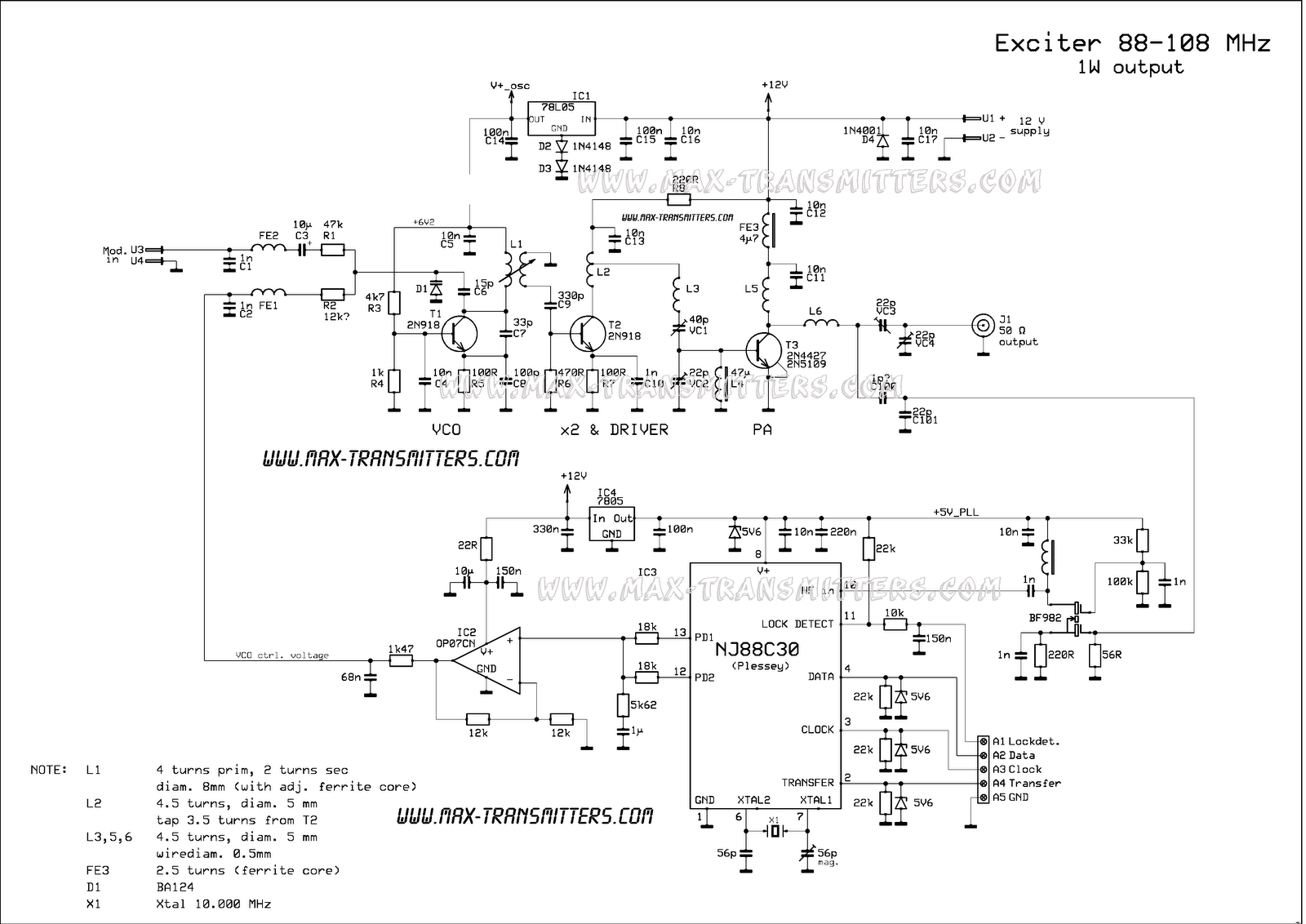
A compact FM transmitter designed for educational purposes. The RF section of this transmitter can be easily integrated into various projects. However, utilizing the PLL feature requires knowledge of constructing a serial data link and connecting the LPFM transmitter...
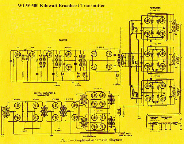
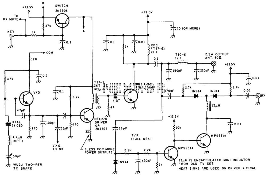
The transmitter was designed with redundancy and cutback (reduced power mode) in mind, giving the transmitter more continuity of service. The final amplifier was divided into 3 separate modules, each using four RCA type UV-898 tubes in push-pull parallel...
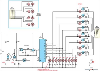
This circuit was developed to create a simple network tester that can be operated by a single individual. Commercial units typically require a second person to monitor the remote LEDs, as the transmitters lack the ability to continuously cycle...
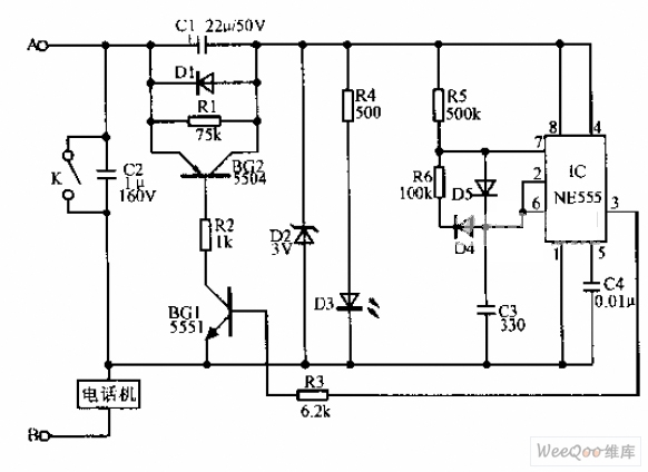
A simple telephone time lock circuit is depicted in the provided diagram. In this circuit, BG1 and BG2 function as electronic switches that are controlled by the IC NE555. When the telephone is on-hook, the DC resistance of the...
An FM radio generates an interference signal that can be detected on another FM radio tuned 10.7 MHz higher than the original. A 50 kΩ potentiometer is used to adjust the modulation level to its maximum without introducing distortion....
Warning: include(partials/cookie-banner.php): Failed to open stream: Permission denied in /var/www/html/nextgr/view-circuit.php on line 713
Warning: include(): Failed opening 'partials/cookie-banner.php' for inclusion (include_path='.:/usr/share/php') in /var/www/html/nextgr/view-circuit.php on line 713