
Ir-Controlled Remote A/B Switch Circuit

The described circuit utilizes an infrared (IR) receiver for A/B control applications, leveraging a pulsed tone-modulated signal to operate a relay. The core of the system includes a photo receptor, designated as Q1, which detects the incoming IR signal. This signal is then processed by an operational amplifier (op amp) IC1, which amplifies the weak signal received from Q1 to a usable level.
Following amplification, the signal is sent to a tone decoder IC2. This component is responsible for demodulating the tone-modulated signal, extracting the relevant control information necessary for the operation of the relay. The output from IC2 is then fed into a flip-flop IC3, which provides a stable output that can be used to control the relay's switching action. The flip-flop ensures that the relay remains in the desired state until a new command is received, enabling reliable A/B switching.
Additionally, the circuit includes an indicator LED system that provides visual feedback on the relay's status. This is managed by IC5, which is designed to turn off the indicator LEDs approximately 15 seconds after the last command is issued. This feature helps in conserving power and reducing unnecessary visual distractions when the system is idle.
Overall, this circuit design is efficient for applications requiring remote control via infrared signals, offering a straightforward yet effective solution for A/B control scenarios. Useful for A/B control, the IR receiver shown controls a relay from an infrared beam that has a pulsed tone-modulated signal. Ql is the photo receptor feeding op amp IC1, tone decoder IC2, and flip-flop IC3. IC5 turns off the indicator LEDs after about 15 seconds. 🔗 External reference
Related Circuits

CMOS switches are utilized to select entries in audio circuits. While these switches can introduce unacceptable levels of distortion, incorporating them into the feedback network of an operational amplifier (op amp) can effectively minimize this distortion. The circuit employs...
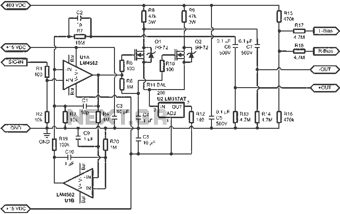
When connected to popular Stax Class 1 electrostatic headphones, the design illustrated in the figures may operate across the full audio bandwidth with a transmission voltage close to 200 Vp-p. Although the resistor divider can be modified to provide...
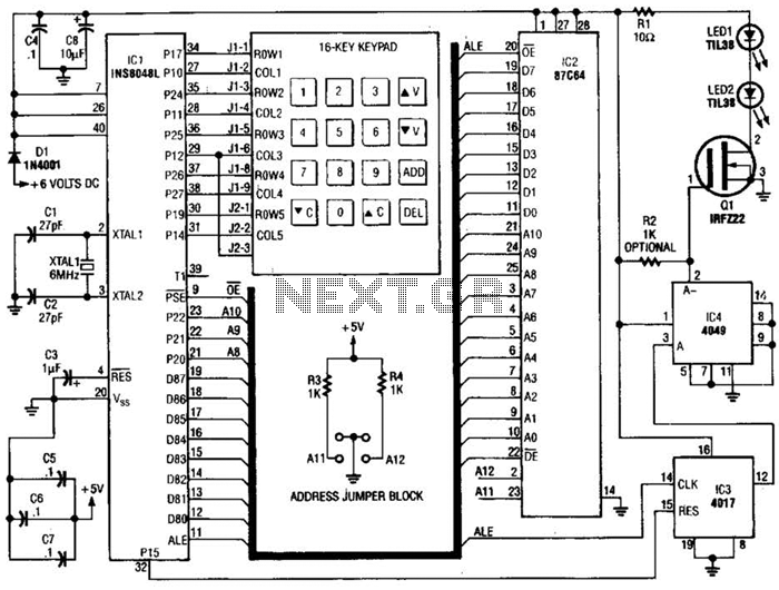
This transmitter emits an FM signal within the 88 to 108 MHz frequency range, featuring a tone of 19 kHz. This tone can activate the FM MPX pilot carrier indicator, allowing interfacing with external devices. L4 is designed for...
There are two independent modeling light circuits for the P2000D, one for each of the two channels. The modeling light circuit is completely separate from the high voltage strobe circuitry, even featuring its own On/Off switch. Therefore, the functionality...
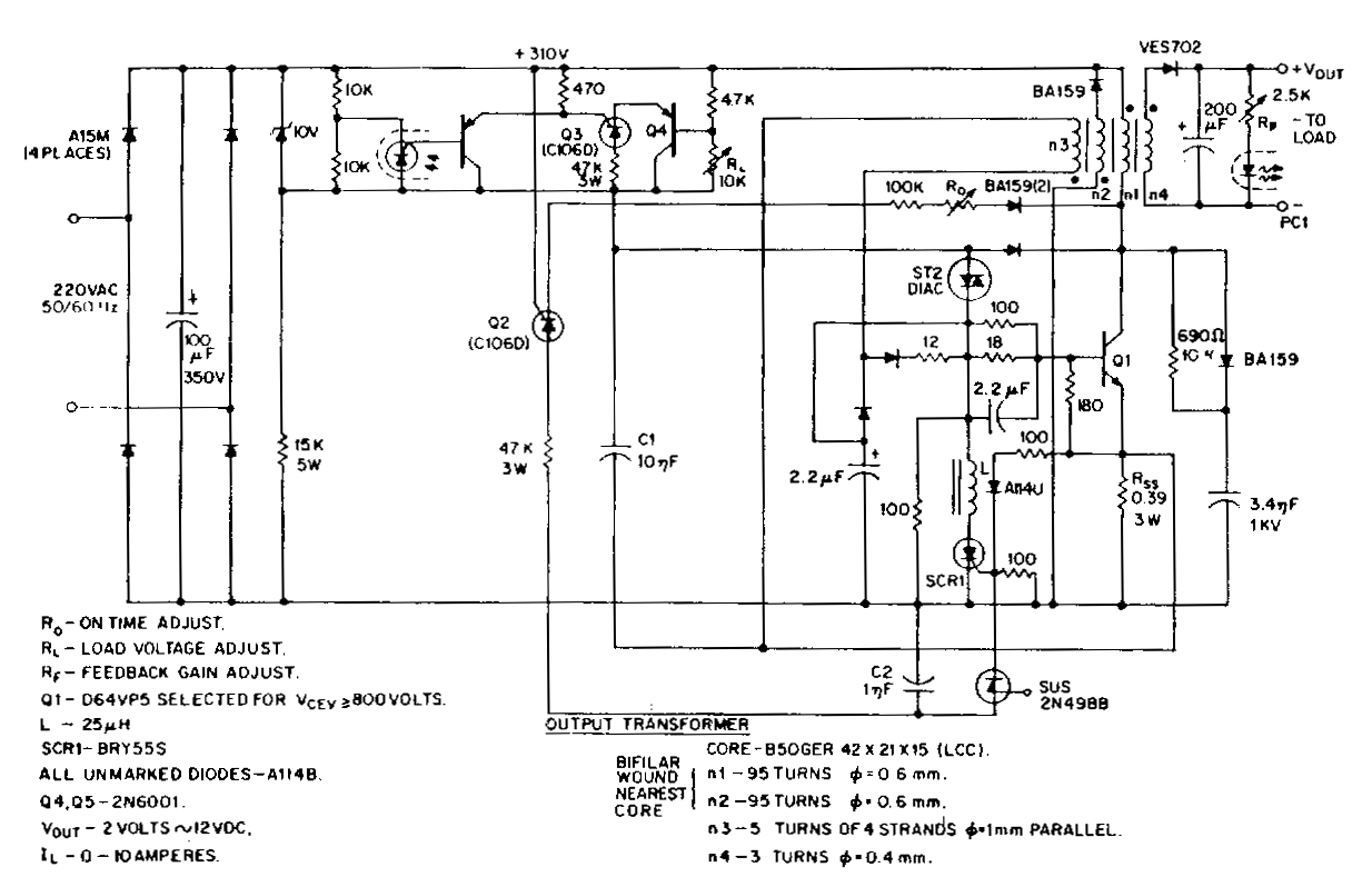
This low-voltage, high-current output switching power supply operates from a 220 VAC input. In this circuit, an ST2 diac relaxation oscillator, along with Q3, C1, and the diac, initiates the conduction of the output switching transistor Q1. The on-time...
Bluetooth is an open wireless technology standard for exchanging data over short distances between fixed and mobile devices, utilizing short wavelength radio transmissions to create personal area networks (PANs) with high security. The Bluetooth baseband protocol combines circuit and...