
Bedini Circuit
The described circuit utilizes principles from John Bedini's radiant energy systems, particularly focusing on timed switching mechanisms to optimize energy transfer. The core of the circuit is the Bedini SG (School Girl) and SSG (Simplified School Girl) configurations, which employ unidirectional circuits for energy generation.
A notable feature is the use of a Bedini SG interrupter, which employs rotating contact switches or commutators to manage the magnetic field within the generating coils. This mechanism allows for the rapid release of built-up magnetic energy, creating high-voltage spikes that enhance energy transfer efficiency. The circuit is designed to handle high voltages, utilizing rotating switches or timed relays instead of solid-state components to mitigate the risk of damage.
The setup includes multiple transistor arrangements, typically configured in parallel to increase current capacity and efficiency. The transistors are mounted on a heat sink to manage thermal dissipation. The circuit also incorporates bus bars for effective energy distribution between the components.
For energy storage, the circuit employs capacitors that manage the voltage and current levels, allowing for efficient charging of the primary battery. The arrangement of coils and transistors can be modified to suit different energy requirements, with the potential for significant amplification effects due to the properties of the transistors used.
Overall, this circuit represents a sophisticated approach to harnessing radiant energy through innovative switching techniques and careful component selection, emphasizing the importance of configuration in maximizing energy output and efficiency.The power is all in the timed switching process. There are two main principles I use of switching the radiant energy the John Bedini way. First, the SG/SSG, Icehouse unidirectional circuit or John Bedini Monopole with the School Girl Circuit (SG) Mechanical-Oscillator-Energizer and second, the John Bedini/Ron Cole switching oscillator circuit. Since my SSG4a/SG4a is a John Bedini/Ron Cole switching oscillator circuit, I should have called it BC4a meaning Bedini/Cole4a.
(just to get the facts straight :) The main difference is the transistor arrangement of the first, usually in parallel, meaning for every wire a transistor/multiplying the J. Bedini circuit on the same heat-sink, which is used mainly for charging batteries and driving the rotor.
New to us of course is the handle of the "Bedini SG Interrupter" meaning the interrupting, of a built up magnetic field, by the proper rotating contact switches or commutators with brass brushes, used to abruptly change direction or abruptly releasing the building tension of that magnetically charged field of the generating-coil side before the spinning magnets are collapsing it like in the SG 1:1 coil unidirectional charging side (the HV spikes), therefore shocking the generating-coil system only. Since the voltages of the bigger machines are to high for solid state conductors we use rotating contact switches or timed relays for interrupters creating an energy shock in the generator-coil windings also called "sharp gradient" through the FWBR, thereby producing rectified pulsating scalar HVDC and therewith radiantly pulse/switch-charging the primary battery in the off time with a very high scalar voltage but minute current by using the in-line capacitor.
This in turn places the primary battery(s), which runs the machine, in a constant charged mode producing the self runner. For the excess voltage we skip the in-line but are using a parallel cap for capacity towards an effective load.
Don't confuse the switch-commutator being a direction changer with the pulse-commutator which is used on the low voltage unidirectional system side for the Ed Gray tube, see BTGRE. For the big power, study "The Bedini-Tesla-Gray Radiant Energy" self running home power set up. Although you can accomplish the big power picture with any of the above mentioned systems by tackling it in different upgrading tasks.
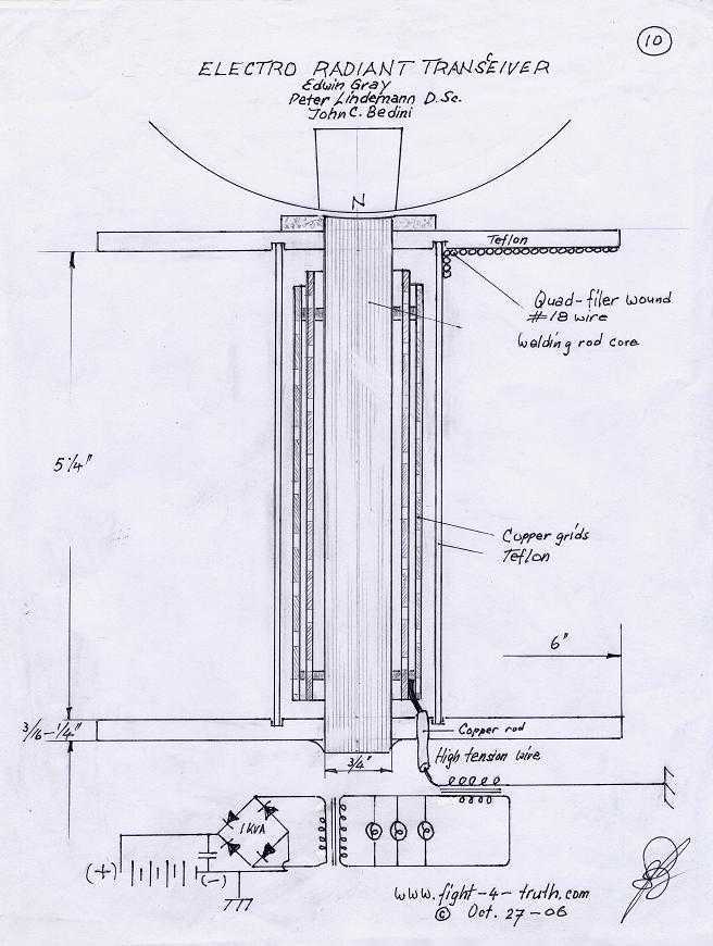
Switching the "Big Six or Eight" In continuation of the replication page, I must tell you that I changed a few things around. First I removed all the wires from my 8-coiler, left two coils and removed the others. Squashed a couple of 1/2" copper pipes, didn't have any 3/4 K-copper, which is the stuff the plumbers use for H2O house service lines (heavy wall pipe, match the cross sections of the twisted wire), then I soldered up four transistors according image 8 above, used two #8 wires for bus bars off the transistor terminals, pos.
and neg. each, ensuing the two coils in parallel and set everything up. Anyhow I'm getting ahead of myself, the drawing above is the result of my new setup. Another reason for piggy backing a second coil to one plate is having looked at the "Big Boy". Although I think the principal of the "Big Boy" is slave/ motor coil and generator coils. Looking at the book, multiplying the single SSG transistor did not make any sense to me at first, until I mounted all four on the plate and studied the setup. That some transistors have a negative resistance region, has come across clearly, but how to comprehend it, is another thing.
Never the less, perhaps picking the energy up through the switching transistors into the bus bar, instead direct off the plate, like I have been doing it, might speed up the whole operation. Realizing that two or more bipolar transistors hooked up in parallel might have an amplification effect like a differential amplifier, which would not really surprise me knowing that John Bedini is a specialist in transistor amplification.
Thus I hooked up the four transistors and everything according my feelings (the Lord's help), with the same ohm setting for max. VAC output off the coils (from before with one transistor setup only, since I never managed the wheel to reach the sweet spot) and gave the 12" 8-mag wheel a good spin by hand.
When I flicked the switch, the wheel took right off like I gave it a kick and so did the needle of the charging voltmeter. At first the motor drew 4.5 amps then it dropped down to 3.8 then to 3.0 then it settled to the sweet spot at 2.5 amps just-a-hummin..
with a charging reading into the batteries at 0.3amps. Besides my pounding heart of joy, I was getting quite worried, whether my feeble wheel would stand this high RPM with those big magnets, the mags didn't have much gluing surface and my copper strapping was not very tight either... it was really creating wind. I ran it for about an hour, taking some readings at 4.30 in the morning. Be careful with this one, you are dealing with kilo volts at the generator and bridge! Sitting back pondering about this set-up, it wouldn't surprise me, if John Bedini's big ten-coil-monopole has a similar coil arrangement as above, recalling JB's comment to Marcus of February 2 - 2005, regarding his ten coiler: " the coil arrangement is something that I can not talk about".
We all know that John Bedini can't talk about KV. How about four drivers and six radiant energy generator coils in series for pure cold RE kilo volts?? I realize according to JB's note of # 984 /Feb. 2/05 there is quite a bit more to his ten coiler with its scalar fields then what I might be coming across with.
I have no intention to oversimplify an inventors work of brilliance!! http://tech.groups.yahoo.com/group/Bedini_SG/message/984 Don't be disheartened about # 984, but remember my earlier comment of above: It also testifies of the forgiveness of little mistakes or changes without sacrificing too much output or efficiency of this machines. ----> Use 12 strands twisted of No. 18 gage 300 feet long on your big coils, then you have something!! When I write Tesla series wound (with the Bedini-twist), I am referring to my sketch Image12 INDEX "Enhanced conductors" in my Work Shop page.
You will realize in the update below to skip the twist and wind either single or 4-filar wires for the generator coils. Join neg.and pos. buses from slave coils on the SCR side contrary to my drawing, I did it just for my convenience. Multiply the main-bus cross sections by the number of coil buses. W.o. words, a 6-coiler main-bus cross section is 6 times of a #8 bus, which in turn would be the size in front and after the SCR.
Whenever I think of the SCR I hear the strong steady click-click -click of the RE spikes, which I indeed can feel if I place my hand on the charging wire :) 🔗 External reference
Related Circuits
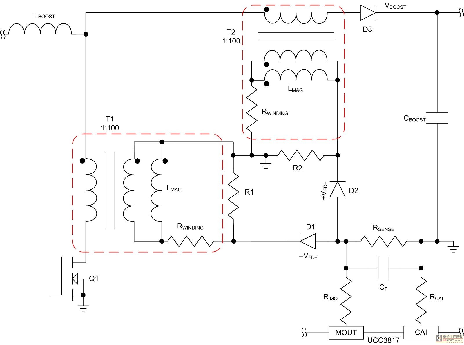
Mode control of the average current (CMC) is necessary to regulate the overall waveform of electric current during the rebuilding cycle. This text recommends selecting specific parameters related to the voltage transformer and outlines steps for designing a circuit...
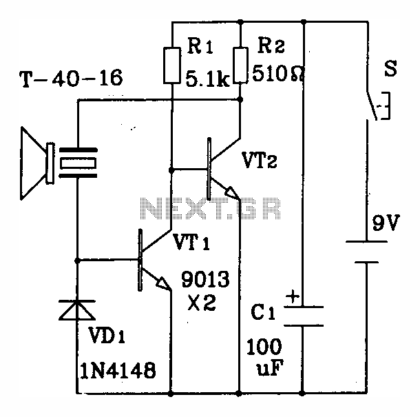
The discrete components ultrasonic transmitting circuit T/R-40-16 is capable of emitting a series of ultrasonic signals at a frequency of 40 kHz. This circuit operates at a voltage of 9V, with an operating current of 25 mA, and can...
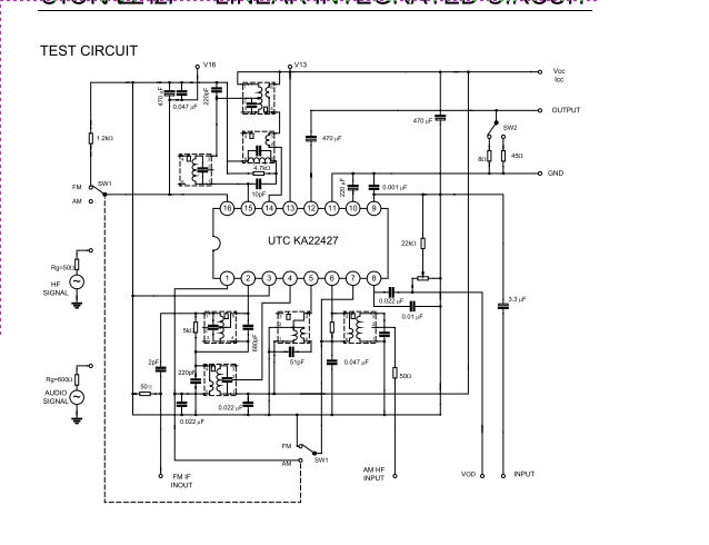
The UTC KA22427 is a single-chip AM/FM radio integrated circuit designed for portable radio applications. It features an AM amplifier, local oscillator, AM mixer, AM/FM amplifier, AM AGC, and FM AGC circuitry. The UTC KA22427 integrated circuit is engineered to...
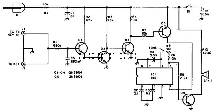
For use with low-power transmitters that require a positive keying voltage. The transistors Q1, Q2, and Q3 are configured as a switching amplifier. When the key is pressed, the collector of Q3 is pulled to ground, which activates Q5...
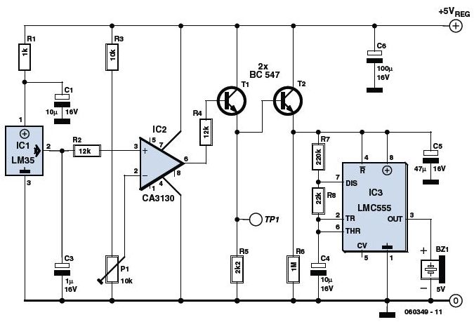
This is an Overheat Detector Alarm Switch using the Temperature Sensor IC LM35. The core of this overheat detector (fire alarm) circuit is a precision integrated temperature sensor, the LM35 (IC1), which provides an accurately linear and directly proportional...
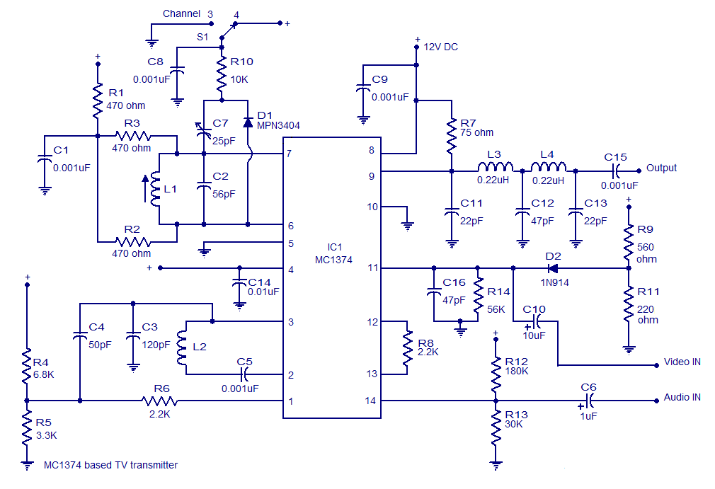
A very simple and high-quality TV transmitter circuit based on the IC MC1374 is presented in this article. The MC1374 is an integrated TV modulator circuit suitable for various TV transmitter applications. It encompasses all necessary circuitry required for...
Warning: include(partials/cookie-banner.php): Failed to open stream: Permission denied in /var/www/html/nextgr/view-circuit.php on line 713
Warning: include(): Failed opening 'partials/cookie-banner.php' for inclusion (include_path='.:/usr/share/php') in /var/www/html/nextgr/view-circuit.php on line 713