
Multivibrator infrared transmitter circuit
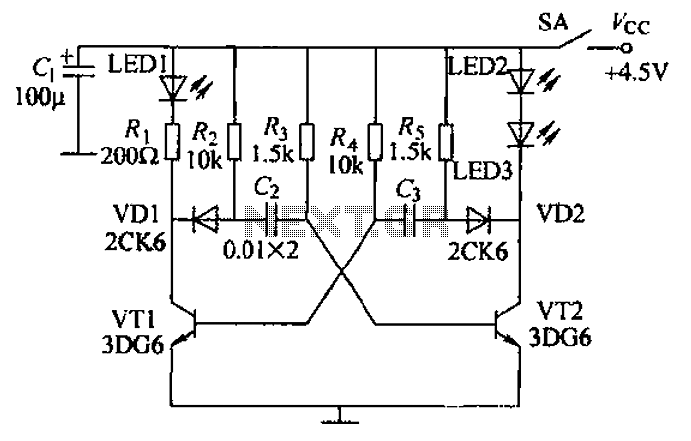
Transistor-based multivibrators are fundamental building blocks in electronic circuits, often used for generating square wave signals. In this configuration, transistors VT1 and VT2 operate in a feedback loop, where the charging and discharging of capacitors Ca and C2, along with the resistors Ra, R4, and Vr2, dictate the timing characteristics of the oscillation. The inclusion of diodes VD1 and VD2 ensures that the base currents are controlled effectively, preventing unwanted conduction states that could disrupt the oscillation.
The frequency of oscillation can be adjusted by varying the values of the resistors and capacitors in the circuit. For instance, increasing the capacitance of Ca or C2 or increasing the resistance values of Ra or R4 will result in a longer charge and discharge time, thereby reducing the frequency of the output signal. Conversely, decreasing these values will increase the frequency.
The output from the collectors of VT1 and VT2 is used to drive multiple LEDs, which not only serve as indicators of the circuit's operational status but also illustrate the alternating nature of the multivibrator's output. The infrared LEDs (LED2 and LED3) can be used in remote control applications or other infrared signaling tasks, while the visible LED (LEDI) provides a simple visual confirmation of the circuit's activity.
Overall, the described multivibrator circuit is a versatile and effective solution for generating oscillating signals in various electronic applications, offering both visual feedback and the potential for further integration into larger systems. By transistors VT1, VT2 and RC components, etc. to form a multivibrator. Multivibrator works: Ra, R4 are VT2, VT1 base bias resistor, closing the switch SA after the power volt age, VT2 priority conduction through its collector plate was low O this low level by VD2, Ca is coupled to the base of VT1 together make VT1 off. After VT2 conduction, R4, VD2 and Vr2 charge to G, the charge is to bring G left positive and right negative charges r make VT1 base potential starts to rise.
When the base current pressure is increased to a certain value, rri conduction, the collector under the jump substation level by VD1, C2 is added to the base VT2, VT2 by conduction to make the deadline. A moment later. VT1 turned off. VT2 conduction. VT1, VT2 variant for turning on and off, so to the cycle continues, so do the glenoid q4 multivibrator.
The oscillation frequency depends on the charge and discharge time constant and G breeze Island. VT1, VT2 after the start-up alternately turned on and off, then on its collector LED2, LED3 and LEDI alternately emit infrared light red shade.., LED visible light is used to monitor the oscillator is working properly or not, that is the working condition.
Related Circuits
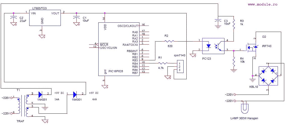
This is a simple schematic designed to control a lamp using a Sony TV remote control. The circuit employs a PWM signal connected to a photocoupler, which isolates the power section from the microcontroller. The power section features an...

The utility vehicle anti-theft alarm circuit consists primarily of two main components essential for its operation. The security circuit is activated when the vehicle owner departs from the vehicle, utilizing an anti-theft switch (S B) to engage the alarm...
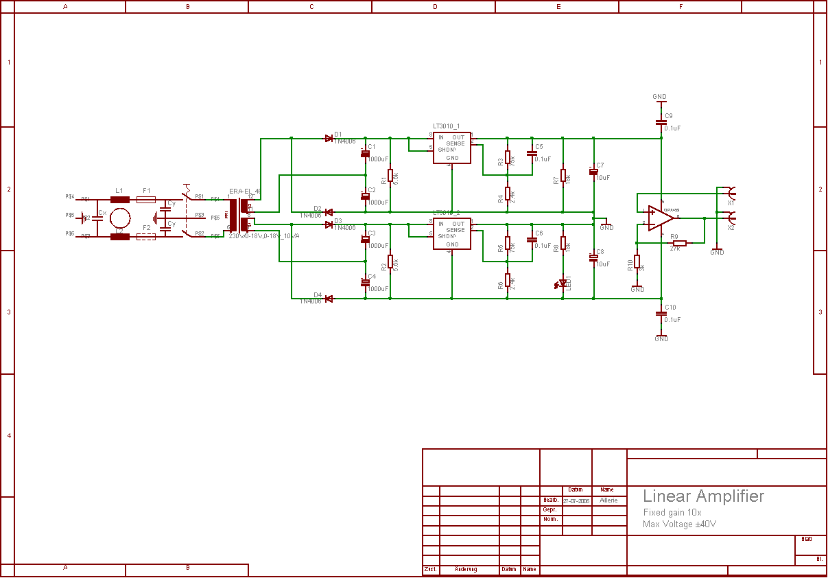
The aim of this project was to develop a linear analogue amplifier designed for laboratory use. This amplifier has to realise a voltage amplification of 10x and is intended to amplify function generator signals for tests. Power supply requirements:...
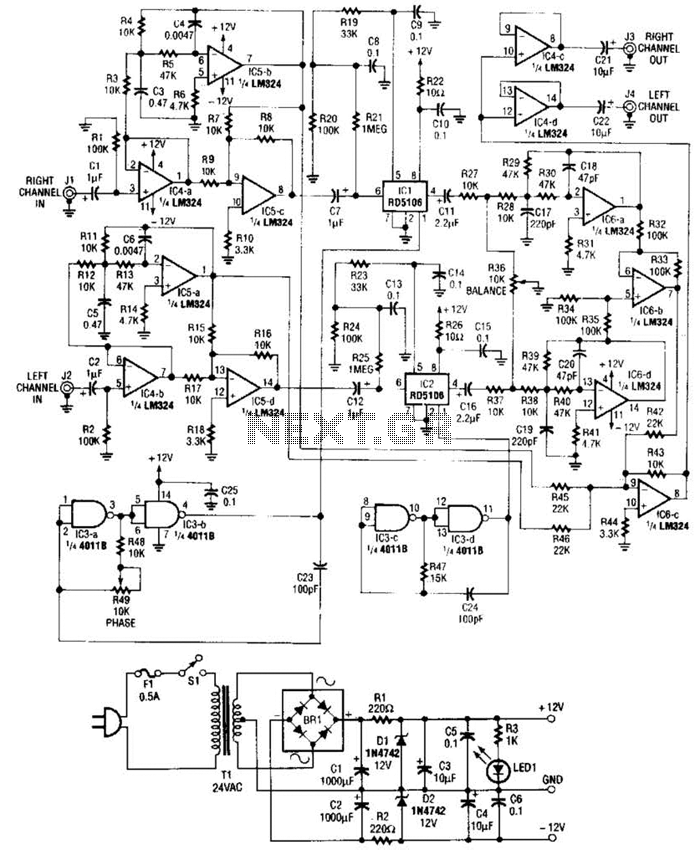
Right- and left-channel signals pass through buffer amplifiers C4-a and C4-b into the active crossover IG5. Low frequencies are directed to mixer IC6-c, while middle and high frequencies are sent to analog delay lines 1C1 and 1C2. The output...
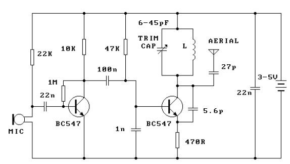
This FM transmitter circuit is very simple and has acceptable transmission. The signal transmitted from this FM transmitter circuit can be received at almost 300 meters in open air. The circuit requires a 3-volt operating voltage and can be...
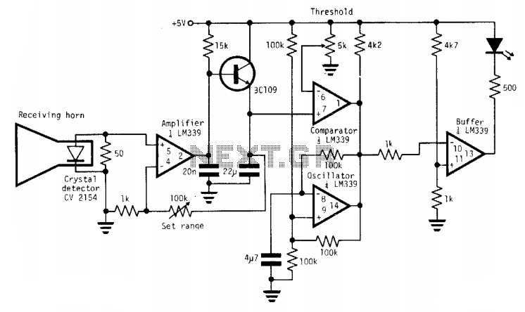
A simple X-band radar detector can indicate changes in RF radiation strength at levels as low as 2 mW/cm². When radiation strikes the detector diode, it generates a voltage at the input of an amplifier. The gain of this...
Warning: include(partials/cookie-banner.php): Failed to open stream: Permission denied in /var/www/html/nextgr/view-circuit.php on line 713
Warning: include(): Failed opening 'partials/cookie-banner.php' for inclusion (include_path='.:/usr/share/php') in /var/www/html/nextgr/view-circuit.php on line 713