
30MHz 500 watt linear tube amplifier

T1 is a 4:1 balun wound on a 5cm ferrite rod. 9 + 9 turns. Connect the end of the first winding to the start of the second to form the center tap. L1 is 9 turns of 3mm Dia wire, wound on a 25mm Dia, 60mm long former. L2 is 18 turns on a toroidal former. Use two lengths of 2mm Dia wire, one with 11 turns and the other with 7 turns. The 50 watt 100 ohm resistor recommended by PA0FRI is formed by two 50 ohm 25 watt non-inductive TO-220 resistors in series, bolted beside the fan. A method involving 100 x 10K carbon resistors arranged 10 x 10 between two pieces of 0.1" matrix wiring board (veroboard) is suggested as a cost-effective alternative that avoids the need to mount input circuitry above the chassis. All inputs are kept below the chassis while the valve anode terminals and output circuitry are also maintained below the chassis. The 100pF trimmer capacitor is adjusted for best VSWR from the driving transmitter at 29 MHz.
All four valve heaters (40 volts each) may be wired in series and connected to the 220 volt mains via a 6µF 250V AC capacitor for 50 Hz (5µF for 60 Hz). An alternative approach is to utilize a 40 volt transformer winding on a home-made transformer to run all the valve heaters (in parallel) as well as the 40 volt fan, which reduces strain on the cathode/heater insulation of older tubes.
PA0FRI suggests a power supply circuit that is switchable and delivers 325 volts, 650 volts, or 1300 volts to the amplifier. The circuit design includes a transformer with various windings: two 120 volt primaries, a 40 volt secondary, and an 1100 volt secondary. The transformer construction is critical; all old wire should be stripped if of poor quality, and laminations should be well insulated.
When winding transformers, it is recommended to measure the available winding area and fill 16% of it with 0.7mm enameled wire, counting the turns. An identical winding of the same number of turns should be added, followed by a third winding using the same gauge but only 36% of the number of turns, and a fourth winding using ten times the number of turns with 0.2mm enameled wire. All windings must be well insulated from each other, with the fourth winding divided into sections, insulated with waxed paper rather than adhesive tape.
The two primaries can be connected in series for 240 volt operation or in parallel for 120 volt operation. It is essential to check with a resistance meter that the transformer windings are isolated from each other and from the case. When testing the transformer, it should be connected to the mains without a load, using a mains 100 watt light bulb in series. This allows for checking that the secondaries produce approximately 40 volts and 1100 volts, indicating correct winding orientation and construction integrity.This is the circuit of a 500 watt linear amplifier, based upon a design by Frits Geerligs, PA0FRI. The circuit uses four PL519 TV line output valves in a very simple circuit that will deliver over 450 watts at 3.5 MHz (350 watts at 30 MHz). PL519 (40KG6A) is a more robust replacement for the earlier PL509 (40KG6) tube. Both valves will work well in this circuit. The input drive power is about 50 - 100 watts so it is compatible with most amateur radio HF transmitters.
Not shown in the circuit is the cooling fan that is required to force air around the valves to cool them. In operation the 1K0 pot is adjusted to set the total valve anode current to around 50mA to 70 mA. T1 is a 4:1 balun wound on a 5cm ferrite rod. 9 + 9 turns. Connect the end of the first winding to the start of the second to form the center tap. L1 is 9 turns of 3mm Dia wire, wound on a 25mm Dia, 60mm long former. L2 is 18 turns on a toroidal former. Use two length of 2mm Dia wire, one with 11 turns and the other with 7 turns. The 50 watt 100 ohm resistor recomended by PA0FRI is formed by two 50 ohm 25 watt non-inductive TO-220 resistors in series, bolted beside the fan. I use 100 x 10K carbon resistors aranged 10 x 10 between two pieces of 0.1" matrix wiring board (veroboard).
My method is cheaper and avoids the need to mount input circuitry above chassis. All inputs are kept below the chassis whilst the valve anode terminals and output circuitry is kept below the chassis. The 100pf trimmer capacitor is adjusted for best VSWR from the driving transmitter at 29 MHz. All four valve heaters (40 volts each) may be wired in series and connected to the 220 volt mains via a 6uf 250vAC capacitor for 50 Hz (5uf for 60 Hz).
I personally favour the use of a 40 volt transformer winding, on a home-made transformer, to run all the valves heaters (in parallel) as well as the 40 volt fan. This places less strain on the cathode/heater insulation of old tubes that may have been kicked around in junk boxes for years.
PA0FRI sugests a power supply circuit which is switcheable and delivers 325 volts, 650 volts or 1300 volts to the amplifier. The circuit is very clever, and shown below for your interest. All the old wire was stripped from the transformer as this was of a poor quality (I don't even think it was copper!!).
All the laminations were varnished and the 1300 volt secondary was VERY well insulated from the other windings. The windings were: 120 volt primary 120 volt primary 40 volt secondary 1100 volt secondary Winding transformers can be quite involved and I am writing an article for this on another page.
But, here is the basic method I used. Measure the available winding area and fill 16% of it with 0.7mm enameled wire, counting the turns. Add an identical winding of the same number of turns. Add a third winding using the same guage but only 36% of the number of turns. Add a fourth winding using ten times the number of turns and using 0.2mm enamelled wire. All windings must be well insulated from each other and the fourth winding must be wound in about five sections, each insulated from the other. I use waxed paper for insulation. Do NOT use adhesive tape, masking tape or sticky backed insulating tape. Connect the two primaries in series for 240 volt operation or in parallel for 120 volt operation. Check, with a resistance meter, that the transformer windings are isolated from each other and the case.
When electrically testing the transformer, connect it to the mains without a load; the mains power in series with a mains 100 watt light-bulb. Check that the two secondaries are about 40 volts and 1100 volts. If the lightbulb lights up then you have got one of the primaries the wrong way round, or there is a fault in transformer construction.
🔗 External reference
Related Circuits
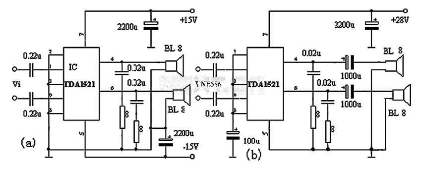
The TDA1521A amplifier circuit is designed for high-fidelity applications with minimal external components. It is suitable for powering Walkman devices or transforming low-powered computer speakers. The TDA1521A comes in a nine-pin single in-line plastic package and offers output power...
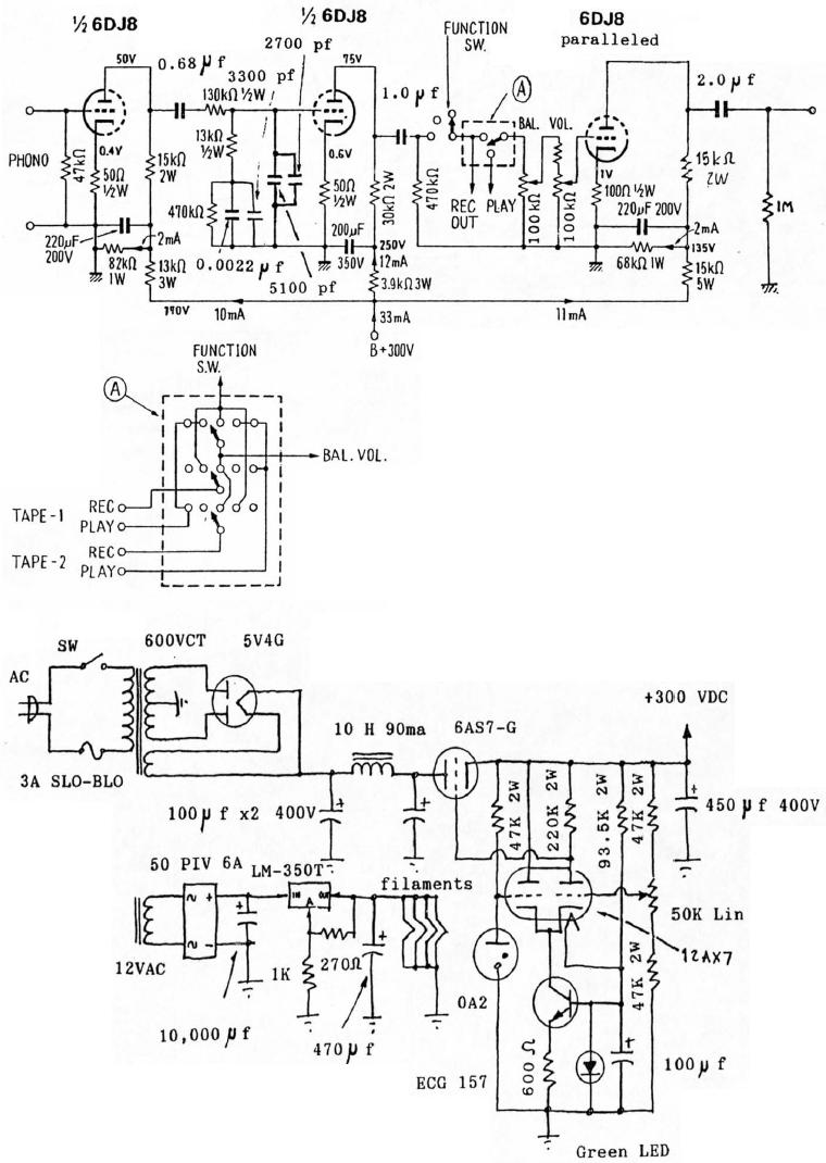
6DJ8 Tube RIAA Phono and Line Preamplifier Schematic. The high-tension (HT) power supply employs tube rectification and regulation. The 6DJ8 tube RIAA phono and line preamplifier schematic is designed to amplify audio signals from phono cartridges and line-level sources, utilizing...
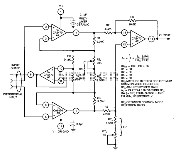
This circuit utilizes a CA5470 quad microprocessor BiMOS-E operational amplifier. Amplifiers A1 and A2 are configured as a cross-coupled differential input and differential output preamplifier stage, while A3 is responsible for input guard-banding. Additionally, amplifier A4 converts the differential...
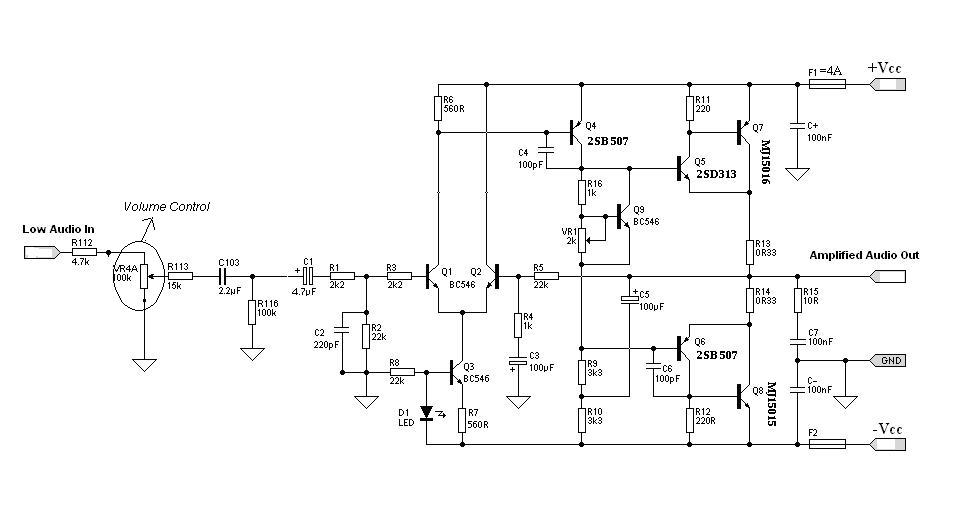
Designing an audio amplifier from scratch using discrete components is an engaging task, as it enables users to create amplifiers that meet diverse requirements. Audio amplifiers can enhance low-level sounds from mobile devices, making them louder and more vibrant....
The schematic has been modified slightly to improve the tone control performance (04 Jan 2002). A new schematic is now on line - the differences are relatively minor, but make the component values for the tone controls a bit...
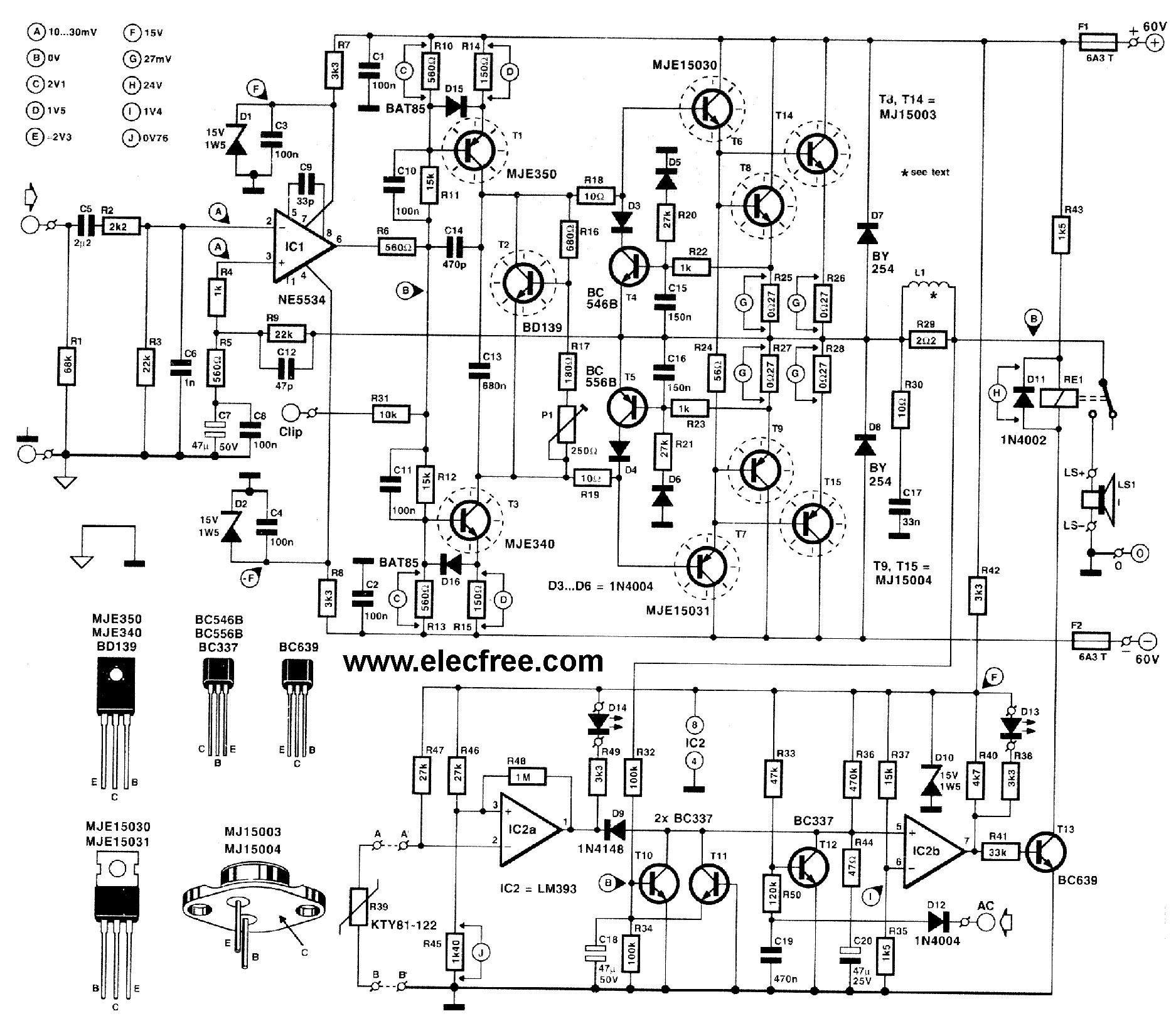
This circuit is designed for friends who are interested in high-power amplifier circuits. It can deliver approximately 300 Watts RMS and operates as an OCL (Output Capacitor-Less) Class AB amplifier, providing high sound power while systematically protecting the loudspeaker...