
6DJ8 Tube RIAA Phono and Line Preamplifier Schematic
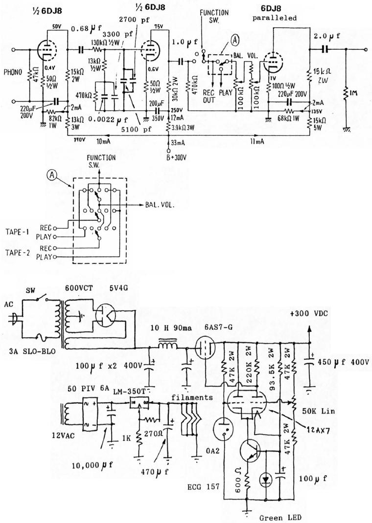
The 6DJ8 tube RIAA phono and line preamplifier schematic is designed to amplify audio signals from phono cartridges and line-level sources, utilizing the 6DJ8 vacuum tube for its amplification stages. The circuit typically includes a dual triode configuration, with one section dedicated to the phono stage and the other to the line stage, allowing for high-quality sound reproduction while maintaining low noise levels.
The power supply is a critical component of this design, featuring tube rectification and regulation to ensure stable voltage levels necessary for optimal tube operation. The use of tube rectification, often implemented with a rectifier tube such as the 5AR4 or similar, converts the AC voltage from the transformer into DC voltage. This process is essential for providing the high-voltage supply required by the 6DJ8 tubes.
Following the rectification stage, a series of filtering capacitors smooth out the rectified voltage, minimizing ripple and providing a clean power source. Additionally, a voltage regulator circuit may be included to maintain consistent voltage levels, enhancing the performance and reliability of the preamplifier.
The RIAA equalization network is incorporated into the phono stage to ensure that the audio signal is adjusted according to the RIAA curve, which is necessary for proper playback of vinyl records. This network typically consists of resistors and capacitors arranged in a specific configuration to achieve the desired frequency response.
Overall, the design of the 6DJ8 tube RIAA phono and line preamplifier schematic emphasizes high fidelity, low distortion, and the warm, rich sound characteristic of tube amplifiers, making it an excellent choice for audiophiles and music enthusiasts.6DJ8 Tube RIAA Phono and Line Preamplifier Schematic. The HT power supply uses tube rectification and regulation 🔗 External reference
Related Circuits
This is the most simple phone busy indicator is possible with only three parts. Connect the circuit so that the green light illuminates when the line is free. If the receiver than the hook, the green LED light is...
Designing a simple yet functional Line Follower Robot (LFR) is a fascinating and challenging topic. The LFR can be implemented in various ways, ranging from a basic two-transistor design to a sophisticated PID (Proportional, Integral, and Derivative) controller that...
This is a linear frequency modulation (FM) detector circuit. This circuit is commonly utilized in telemetry applications and a wide range of analog communication systems. The primary component of this circuit... The linear FM detector circuit is designed to demodulate...
The headlamp schematic for the Daewoo Korando is illustrated in the accompanying figure. It details the connections and wiring between various components of the vehicle's headlamp system, including the alternator, ignition switch, buy-off switch, high lamp relay, low lamp...
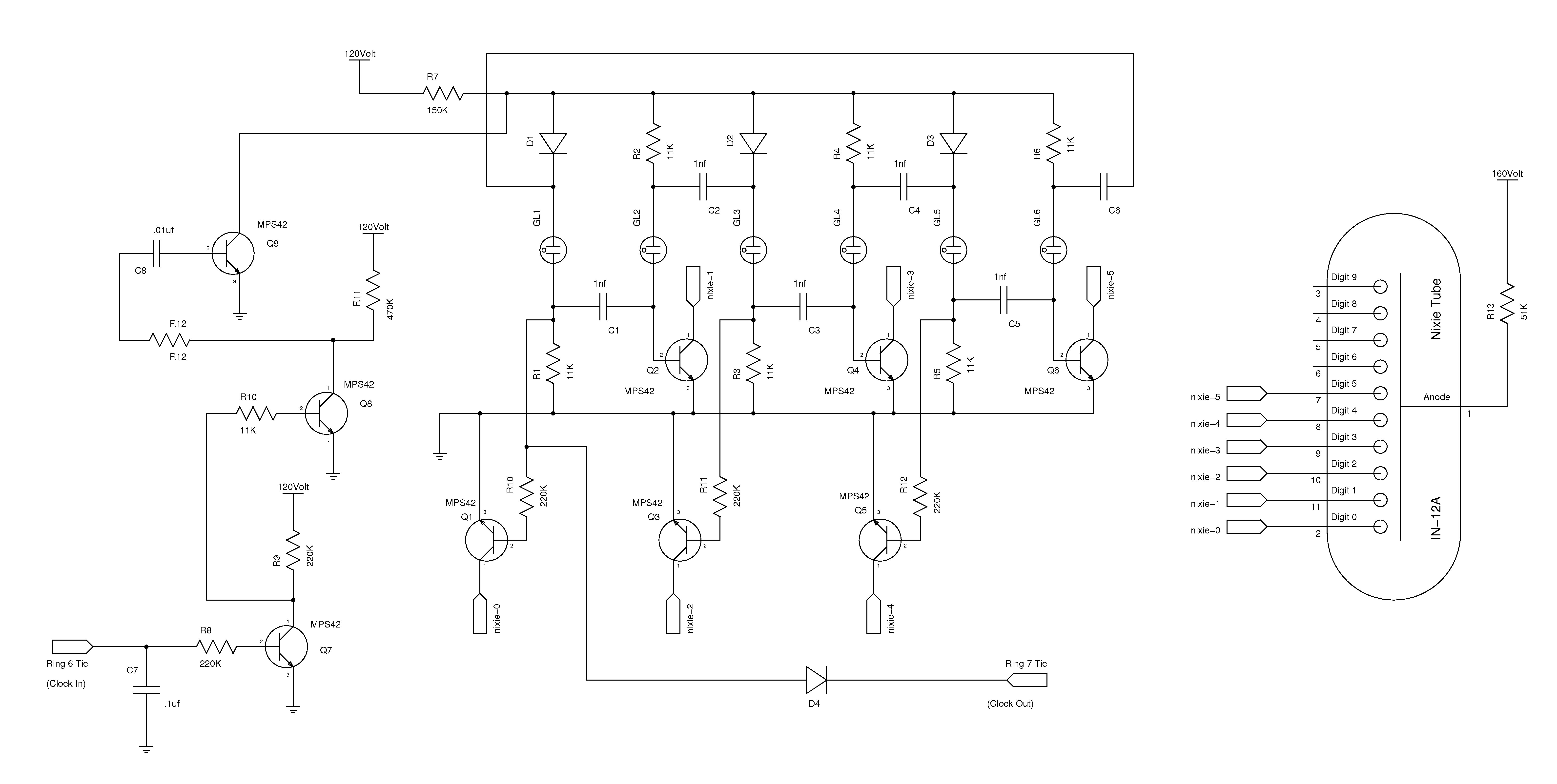
The nixie tube clock consists of a high-voltage power supply, seven ring counters, and an Atmel AVR processor. The power supply is shown in Schematic 1. It takes 12 volts AC and converts it to DC, which drives the...
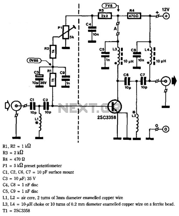
This circuit provides a gain of 10 to 15 dB from 400 to 850 MHz, making it particularly effective in scenarios where the television signal is weak. Additionally, the filters can be customized to meet individual user requirements. Construction...