
XTR108 voltage excitation bridge circuit diagram
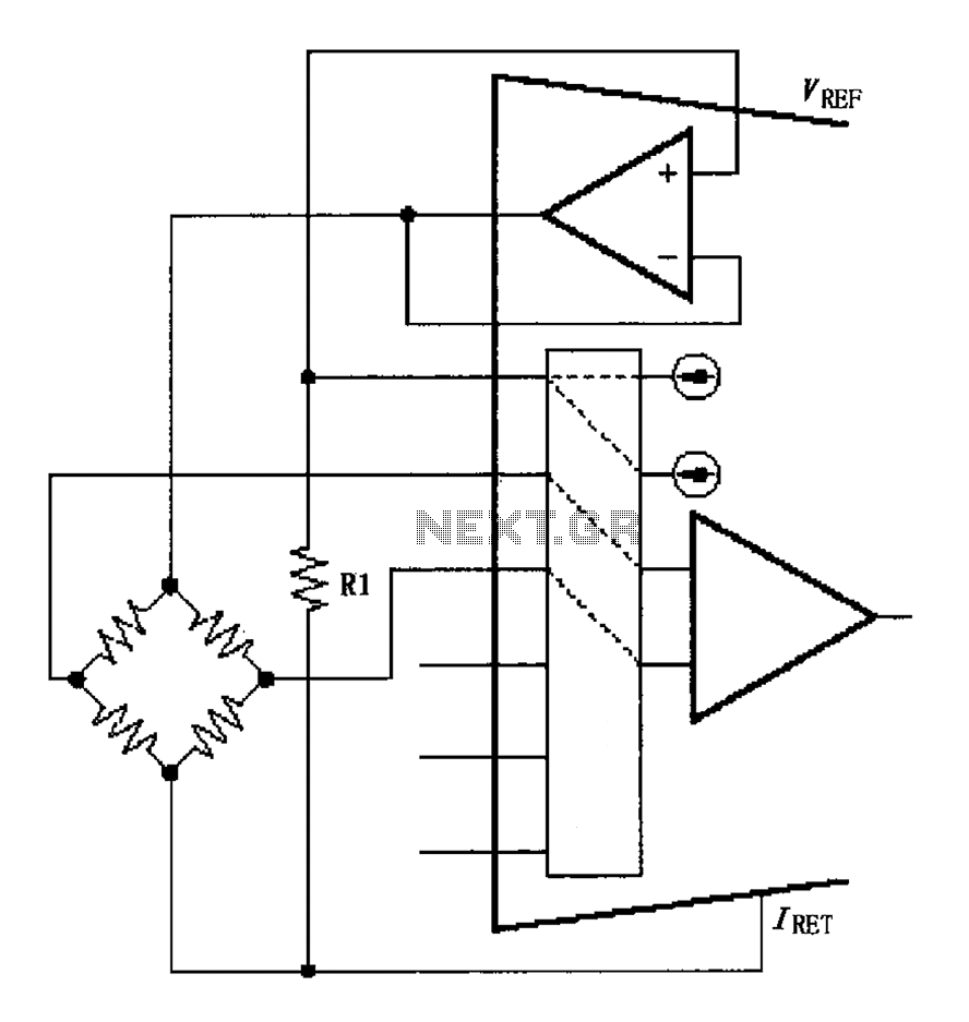
The XTR108 is a precision current loop transmitter designed for use in applications that require the measurement of resistance temperature detectors (RTDs). In this context, the bridge circuit is a critical component that allows for the accurate measurement of temperature by converting the resistance changes of the RTD into a corresponding voltage signal.
The excitation voltage (VEX) provided to the bridge is crucial for maintaining linearity in the output. The relationship VEX = 2IREFR1 indicates that the excitation voltage is twice the product of the reference current (IREF) and the resistance (R1) used in the circuit. This configuration helps to ensure that the output voltage remains proportional to the temperature changes detected by the RTD.
The linearization algorithms applied in this circuit are essential for correcting any non-linearities that may arise from the RTD's response characteristics. By adjusting the excitation voltage and employing these algorithms, the system can achieve a more accurate and stable output, which is particularly important in precision temperature measurement applications.
In summary, the XTR108 bridge circuit effectively utilizes a linearized approach to provide a stable excitation voltage, ensuring that the RTD's resistance changes correspond accurately to temperature variations. This method enhances the reliability and precision of temperature readings in various industrial and scientific applications. As shown for the bridge circuit excitation voltage XTR108. Circuit for the bridge excitation voltage is linearized adjusted, linearized algorithms that RTD linearization same r esponse. Excitation voltage VEX 2IREFR1, where VEX is the excitation voltage at both ends of the bridge.
Related Circuits

The following circuit illustrates an electrical circuit diagram for the MR2 MKII electric aerial. Features include control by an Aerial Control Relay, which consists of... The MR2 MKII electric aerial circuit is designed to facilitate the automatic operation of the...
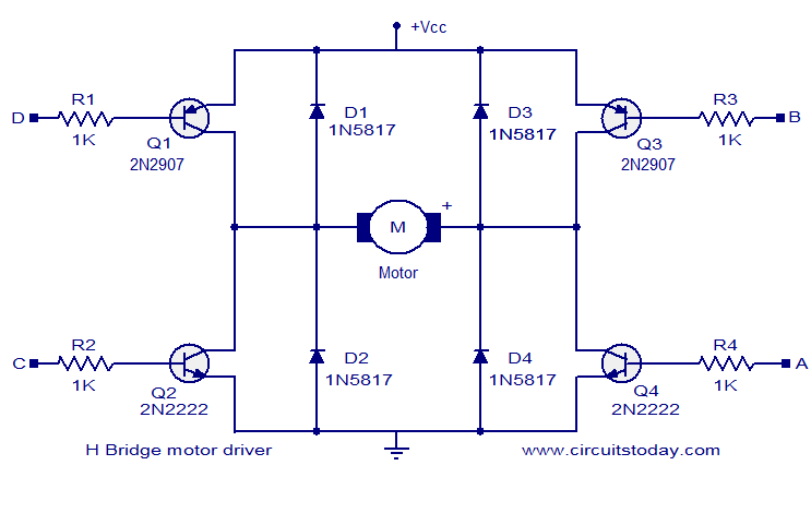
The circuit presented is a simple H-bridge motor driver circuit utilizing commonly available components. An H-bridge is an efficient method for driving motors and is widely used in various electronic projects, particularly in robotics. The circuit illustrated is a...

The basic application circuit for a thermistor is illustrated. Figure (a) depicts a fundamental temperature measurement circuit with limited accuracy, suitable only for applications that do not require high precision. RT represents a positive temperature coefficient thermistor; as the...

The high-temperature alarm will emit a beep and the LED will blink when the temperature of the device rises abnormally. This simple overheating alarm is designed to monitor heat levels. The high-temperature alarm circuit is an essential safety device used...
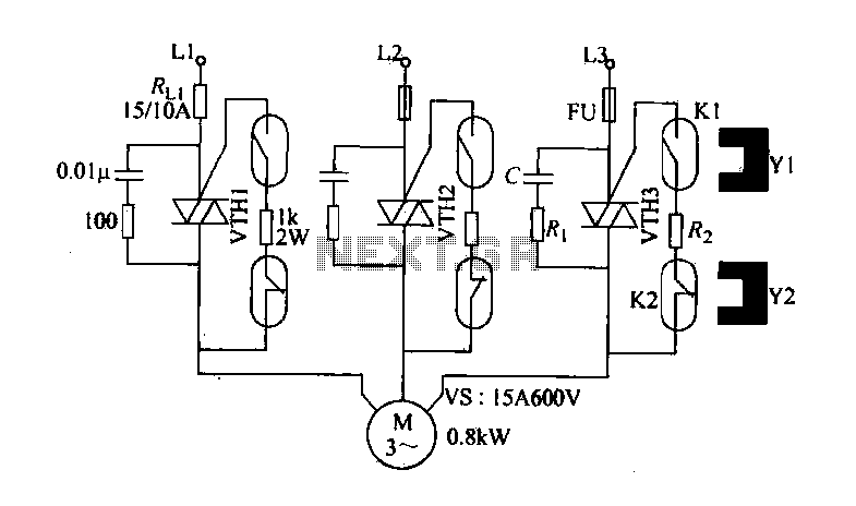
The circuit diagram illustrates a female textile machine power control circuit. VTH1-VTH3 represent TRIACs, while R and C form the absorption line. Rz serves as the triggering current limiting resistor. K1 is designated for starting the reed, and K2...
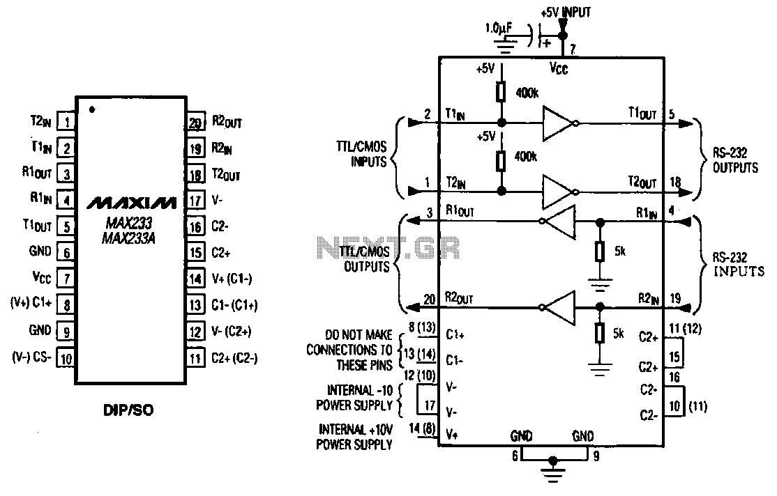
The MAX233 / 233A is a multi-channel data interface circuit featuring dual output and dual input driver circuits. It is designed for small digital products and multimedia equipment to facilitate data transmission. The MAX233 / 233A integrates multiple functions to...