
Linear Resistance Meter

This resistance meter has 5 ranges and it has a forward reading linear scale on each range. The full-scale values of the 5 ranges are 1K, 10K, 100K, 1M &10M respectively and the unit is therefore capable of reasonably accurate measurements from a few tens of ohms to ten Megohms. Most linear scale resistance meters including the present design, work on the principle that if a resistance is fed from a constant current source the voltage developed across that resistance is proportional to its value.
For example, if a 1K resistor is fed from a 1 mA current source from OhmG ‚¬ s Law it can be calculated that 1 volt will be developed across the resistor (1000 Ohms divided by 0. 001 amps = 1 volt). Using the same current and resistance values of 100 ohms and 10K gives voltages of 0. 1volts (100 ohms / 0. 001amps = 0. 1volts) and 10 volts (10000 ohms / 0. 001amps = 10 volts). Thus the voltage developed across the resistor is indeed proportional to its value, and a voltmeter used to measure this voltage can in fact be calibrated in resistance, and will have the desired forward reading linear scale.
One slight complication is that the voltmeter must not take a significant current or this will alter the current fed to the test resistor and impair linearity. It is therefore necessary to use a high impedance voltmeter circuit. The full circuit diagram of the Linear Resistance Meter is given in Figure 1. The constant current generator is based on IC1a and Q1. R1, D1 and D2 form a simple form a simple voltage regulator circuit, which feeds a potential of just over 1.
2 volts to the non-inverting input of IC1a. There is 100% negative feedback from the emitter of Q1 to the inverting input of IC1a so that Q1G ‚¬ s emitter is stabilised at the same potential as IC1aG ‚¬ s non-inverting input. In other words it is stabilised a little over 1. 2 volts below the positive supply rail potential. S3a gives 5 switched emitter resistances for Q1, and therefore 5 switched emitter currents. S3b provides 5 reference resistors across T1 & T2 via S2 to set full-scale deflection on each range using VR1.
As the emitter and collector currents of a high gain transistor such as a BC179 device used in the Q1 are virtually identical, this also gives 5 switched collector currents. By having 5 output currents, and the current reduced by a factor of 10 each time S3a is moved one step in a clockwise direction, the 5 required measuring ranges are obtained.
R2 to R6 must be close tolerance types to ensure good accuracy on all ranges. The high impedance voltmeter section uses IC1b with 100% negative feedback from the output to the inverting input so that there is unity voltage gain from the non-inverting input to the output. The output of IC1b drives a simple voltmeter circuit using VR1 and M1, and the former is adjusted to give the correct full-scale resistance values.
The CA3240E device used for IC1 is a dual op-amp having a MOS input stage and a class A output stage. These enable the device to operate with the inputs and outputs right down to the negative supply rail voltage.
This is a very helpful feature in many circuits, including the present one as it enables a single supply rail to be used where a dual balanced supply would otherwise be needed. In many applications the negative supply is needed simply in order to permit the output of the op-amp to reach the 0volt rail.
In applications of this type the CA3240E device normally enables the negative supply to be dispensed with. As the CA3240E has a MOS input stage for each section the input impedance is very high (about 1. 5 million Megohms!) and obviously no 🔗 External reference
Related Circuits
The PIC Microchip Processor must be programmed before it will function as a Volt & Amp meter. There are many internet sites and PIC programmers that you can use. I used a Microchip MPLAB ICD 2 during the project....
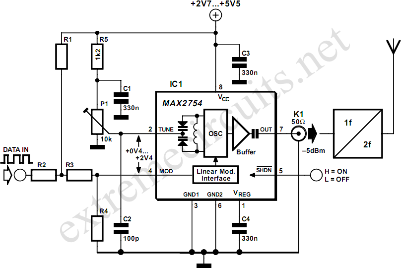
High-frequency voltage-controlled oscillators (VCOs) are challenging to construct, which is why Maxim has developed the integrated 1.2 GHz oscillator, the MAX2754. The center frequency is adjustable via the TUNE input, while a linear modulation input allows for frequency modulation....
Here is a simple technique for measuring frequencies over quite a wide frequency range and with acceptable accuracy limits using a PC. It follows the basic technique of measuring low frequencies, i.e. at low frequency, period is measured for...
This LED thermometer is designed for in home use, to read temperatures between about 60 and 78 degrees Fahrenheit. It is based around a precision temperature sensor IC, the LM34DZ. This sensor require no calibration and can measure temperatures...
A tachometer can be constructed using the TC9400 in frequency-to-voltage (F/V) mode to convert frequency information (RPM) into a linearly proportional voltage. This voltage can then be compared to one of several comparators (in this example, using eight). The...
Many SWR (Standing Wave Ratio) and power meters used by amateur radio operators provide reasonably accurate continuous average power readings with a CW (Continuous Wave) key-down signal. However, these meters may not reliably measure Peak Envelope Power (PEP) or...