
Infrared Proximity Detector circuit

The Infrared Proximity Detector circuit leverages the capabilities of the TSOP4830 to detect infrared light effectively. The circuit's design is based on the principles of modulation and detection, where the TSOP4830 is tuned to a specific frequency, allowing it to discern signals amidst ambient light interference. The dual 556 timer configuration facilitates the generation of modulated infrared signals through two distinct oscillators, each serving a specific purpose in the overall detection process.
In practical applications, the proximity detector is particularly advantageous for model train enthusiasts, as it can accurately detect the presence of trains on tracks without interference from other light sources. The use of an open collector output from the voltage comparator enables easy integration with other electronic components or systems, allowing for versatile applications such as triggering alarms or activating other devices upon detection of an object.
The design considerations for the circuit also include the physical arrangement of the components, ensuring that the infrared LED and TSOP4830 are optimally positioned for maximum sensitivity. The recommended mounting guidelines, including the specified distances between the tubing and the receiver IC, are critical for maintaining the performance of the detector.
To further enhance the usability of the circuit, the inclusion of terminal diagrams allows users to customize their installations according to specific requirements. This modular approach to design facilitates scalability and adaptability, making it suitable for various environments and applications beyond model trains, such as security systems or automated lighting controls. Overall, the Infrared Proximity Detector circuit represents a robust solution for detecting the presence of objects using infrared technology.The circuits on this page are for an Infrared - Proximity Detector using the Vishay Electronics - TSOP4830 "IR Receiver Modules for Remote Control Systems". In this circuit the TSOP4830 is used as a sensitive infrared detector that does not require shielding from room lighting.
The detector will work under almost any lighting condition from comple te darkness to full sunlight. As a guide, if a TV remote control will work in a particular area then so should this circuit as the TSOP4830 would normally used in conjunction with a remote control for a television or VCR. This circuit was designed primarily for Between The Rails detection of model trains but can be used to detect other objects that reflect or block infrared light.
While this circuit will work in almost all light conditions but it can be affected by infrared remote controls. For its designed use this will not be a problem as the light will be blocked by a train car anyway. The following schematic is for a basic version of the Infrared - Proximity Detector used on this page.
The circuitboards offered through this page have 1 LED driver oscillator and 4 or 8 detector circuits on them. In the basic proximity detector circuit, the hand-held remote is replaced by an infrared LED driver that uses a 556 dual timer.
The two oscillators in the 556 simulate the pulsed carrier signal of the remote but without the information such as volume or channel that would normally be sent to an appliance. The upper portion of the circuit uses two astable 556 oscillators, IC 1A and IC 1B to drive an infrared LED.
IC 1A operates at approximately 3Hz with a duty cycle of about 9 percent. IC 1B is adjusted to 30 kHz (the design operating frequency of the TSOP4830) with a duty cycle of about 52 percent. The lower portion of the circuit is the IR detector, time delay and output section. The output of the voltage comparator, IC 3, produces a steady LOW - open collector output when infrared light of the correct frequency is detected by the TSP4830 receiver IC.
When the IR Receiver Module receives a sufficiently strong 30 kHz infrared pulse from D1, its output, pin 3, will go LOW for the duration of the pulse. (About 9 milliseconds. ) When the output of the IR detector goes LOW, the voltage at the PLUS input of comparator, IC 3, will be made LOW and the comparator`s output will go LOW.
As long as the infrared pulses are seen by the receiver module the output of the comparator will remain LOW. The top of the tubing is flush with or slightly higher than the top of the ties. The bottom of the tubing should extend about 1" below the bottom of the infrared receiver IC. The TSOP4830 Receivers are very sensitive and will need to be shielded from all sources of IR signal except the LED that is directly across from the receiver when used in a `Break the Beam` situation.
There are two versions of the circuitboard for the Infrared - Proximity detector. The first version has a single output - LED driver and four detector circuits while the second has a dual output - LED driver and eight detector circuits. The detector portions of the circuits are identical. The individual detector circuits are the same as in the test circuit above. The LED driver circuit is slightly different though, see the "Carrier Frequency Adjustment Notes" section below for details.
The full circuit schematic is too large for practical use so smaller "Terminal" diagrams has been provided that the user can plan, layout and document their own detector systems. The following is a terminal diagram with no input and output connections shown. Print this diagram in the centre of a sheet of paper and use it to plan and document a particular installation.
The individual detector circuits are the same as in the test circuit above. The LED driver circuit is slightly different though, see the "Carrier Frequency Adjustment Notes" section below for details. The full circuit schematic is too 🔗 External reference
Related Circuits

This circuit was originally designed to detect weak flashes of laser light reflected off a fabric video projection screen. It was used as part of a firearm training system. It generates a 100 ms output pulse whenever it detects...
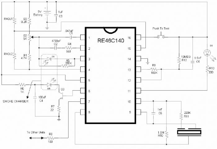
The RE46C140 circuit can be used to design a simple smoke detector alarm with minimal external electronic components. The RE46C140 IC is a low-power CMOS photoelectric smoke detector IC that provides all necessary features for a photoelectric smoke detector...
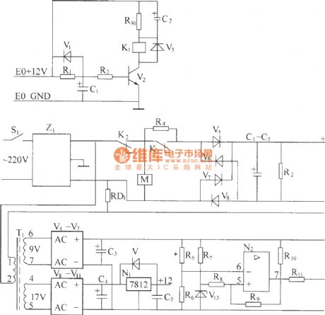
220V (50Hz) alternating voltage passes through the Z1 circuit filter, which filters the signal before sending it to the connection point of the AC overvoltage and undervoltage protection relay K2. During normal operation, the K2 connection point should be...
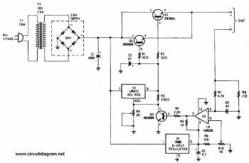
This battery charger circuit is regulated and adjustable, enabling it to charge most NiCAD batteries. It can accommodate both single cells and multiple battery cells connected in series or parallel. The maximum voltage of the batteries should not exceed...
This is a very simple FM receiver built using only one transistor. It does not utilize any chips or other active components. The output is connected to earphones; an amplifier circuit is required if the radio is to be...
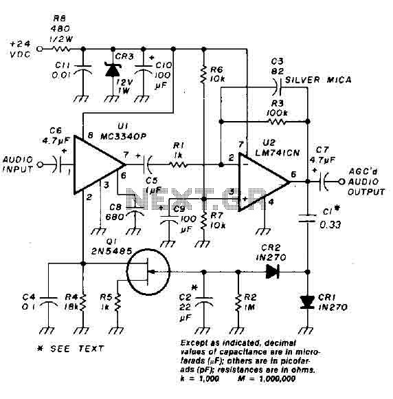
An audio signal applied to the input VI is passed through the operational amplifier 741, designated as U2. After amplification, the output signal V2 is sampled and sent to a negative voltage doubler/rectifier circuit composed of diodes CR1 and...