
4-20 mA current loop circuit
The temperature to current transmitter operates on a 2-wire configuration, which simplifies installation and reduces the amount of wiring required. The 4-20 mA current loop is a standard in industrial applications for transmitting analog signals over long distances while minimizing the effects of noise and voltage drops. In this configuration, the transmitter outputs a current signal that is directly proportional to the temperature detected by the NTC (Negative Temperature Coefficient) sensor.
The NTC sensor exhibits a decrease in resistance as temperature increases, allowing for precise temperature measurements. The transmitter converts the resistance change into a corresponding current output. For example, at a temperature of 0°C, the output might be 4 mA, while at 100°C, it could reach 20 mA. This linear relationship enables easy interpretation of the current signal into a temperature reading.
The loop-powered design means that the transmitter receives its operating power from the current loop itself, eliminating the need for an external power source. This is particularly advantageous in remote or hard-to-access locations where power supply installation may be impractical.
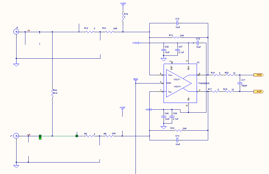
Overall, the U3 temperature to current transmitter provides an efficient and reliable means of measuring temperature and transmitting that information to monitoring systems, making it suitable for various industrial applications, including HVAC systems, process control, and environmental monitoring.Continued from the previous post. The same priciple is true for the followings, temperature to current transmitter. In this case the input voltage is propotional to the measured temperature, not the rotation. Temperature input, full analog, 2 wire, 4-20 mA loop powered transmitter U3 is a low cost, NTC based, integrated temperature sensor. The next.. 🔗 External reference
Related Circuits
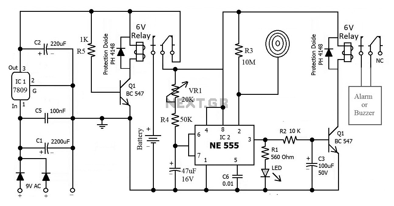
This is the circuit diagram of a touch-activated alarm system that remains operational during power outages. The alarm system is triggered when someone touches the designated touch plate. A notable feature of this circuit is the automatic battery activator,...
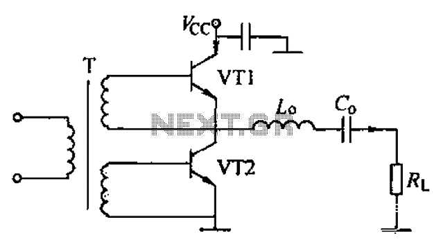
A complementary voltage switching Class D amplifier circuit is presented. Transistors VT1 and VT2 are 3DA12 types, while another transistor, VT3, is of the 3DK41C type. The collector is connected to a constant DC voltage of 12V. The input...
Prior to the test point, there is an AD744 operational amplifier with its output connected to a 10nF capacitor. Following this, a 1kΩ resistor connects to ground. From the junction where the capacitor and resistor meet, a 4.7kΩ resistor...
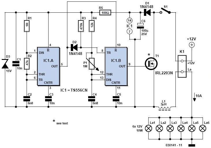
A light dimmer is quite uncommon in a caravan or on a boat. This document outlines how to create one, allowing for mood adjustment when needed. A light dimmer circuit is an essential component for enhancing the ambiance in confined...
The resulting timer circuit is made from a CD4060, includes an oscillator and a 14 stage binary counter, two CD4040's, which are 12 stage binary counters, a CD4012 Dual Nand gate and a CD4013 Dual D Latch. The CD4060...
Crystal 80mW FM transmitter circuit diagram of the production The Crystal 80mW FM transmitter circuit is designed to generate frequency modulated (FM) signals suitable for short-range audio transmission. This circuit primarily consists of a crystal oscillator, which serves as...