
4-20mA simulation circuit for PLC

The circuit design for simulating sensor inputs to a PLC utilizing the XTR series devices, particularly the XTR116 or XTR117, involves creating a 2-wire current loop transmitter. The XTR116 is advantageous due to its enhanced features, including a precise voltage reference, which can improve output accuracy.
For the circuit, the input voltage range can be set between 0.8V to 4V, corresponding to the desired output current of 4-20mA. The output current can be configured to extend from 0 to 24mA by adjusting the reference voltage and using an offset current. This is achieved by connecting additional resistors and possibly a potentiometer to fine-tune the output.
The XTR116 and XTR117 both support a simple configuration, where the output current is determined by the input voltage applied to the device. The inclusion of a linear regulator in the XTR117 allows for stable operation at 12VDC, while the XTR116 can be configured similarly but may require additional components to achieve the same level of performance.
When designing the circuit, it is essential to consider the power supply requirements, ensuring that the voltage levels are appropriate for the operation of the selected XTR device. The datasheets provide application diagrams that illustrate how to implement the circuit effectively, including the necessary calculations for determining the resistor values needed for the desired output current.
In summary, either the XTR116 or XTR117 can be utilized to simulate sensor inputs for a PLC, with careful consideration of the circuit design and component selection to achieve the desired output characteristics. The choice between the two devices should be based on availability, required precision, and specific application needs.I am looking for a simple circuit to simulate sensor inputs to PLC. Sensors take 12VDC and outputs 4-20mA. I was looking at your XTR series devices which seems to be able to achieve this but I am not sure which one will be ok to use for 12VDC voltage. Also, it would be good to have the range of output from 0 to 24mA rather than 4-20mA so that we c an test the PLC input for error inputs as well. In particular, the XTR117 could be of interest for you, it includes its own linear regulator, and the input current could be generated using the Regulated 5V output in series with a potentiomenter to control the current output value. Thanks for the help Albert! You`re correct that the XTR117 is likely the best candidate for this type of simple circuit to simulate a 2-wire current loop transmitter.
I have seen couple of answers given previously with circuit diagram and components to suit the requirement. Is it possible to get a schematic and calculations If not I have a circuit calculation for XTR116 which was previously posted so I can work with it.
Ifound a XTR116 in lab at my work but XTR117 is not available so I will have to buy it. For my application, if I use XTR116 rather than XTR117 then do I miss out on anything do I need to keep anything else in mind when using XTR116 instead of your suggested XTR117 I have attached files that I found from one of the other questions on ti. com The XTR116 actually has more features than the XTR117, not less. The XTR116 includes everything that the XTR117 includes with the addition of a more precise reference voltage of 4.
096V. The XTR115 is a similar product with a 2. 5V precision reference. Both the XTR117 and XTR116 are fairly easy products to use and full applications diagrams are included in the datasheet. Figure 1 describes a standard application with a 4-20mA output from a 0. 8V to 4V input voltage. Figure 2 shows how to configure the output for 4-20mA with a 0V minimum input by adding an offset current through the voltage reference.
All content and materials on this site are provided "as is". TI and its respective suppliers and providers of content make no representations about the suitability of these materials for any purpose and disclaim all warranties and conditions with regard to these materials, including but not limited to all implied warranties and conditions of merchantability, fitness for a particular purpose, title and non-infringement of any third party intellectual property right. TI and its respective suppliers and providers of content make no representations about the suitability of these materials for any purpose and disclaim all warranties and conditions with respect to these materials.
No license, either express or implied, by estoppel or otherwise, is granted by TI. Use of the information on this site may require a license from a third party, or a license from TI. Content on this site may contain or be subject to specific guidelines or limitations on use. All postings and use of the content on this site are subject to the Terms of Use of the site; third parties using this content agree to abide by any limitations or guidelines and to comply with the Terms of Use of this site. TI, its suppliers and providers of content reserve the right to make corrections, deletions, modifications, enhancements, improvements and other changes to the content and materials, its products, programs and services at any time or to move or discontinue any content, products, programs, or services without notice.
🔗 External reference
Related Circuits

The TPS61200 specifications indicate that GND serves as the control/logic ground, while PGND is designated as the power ground. However, this distinction is not accurately represented in the symbols used in the diagram. There is also confusion regarding the...
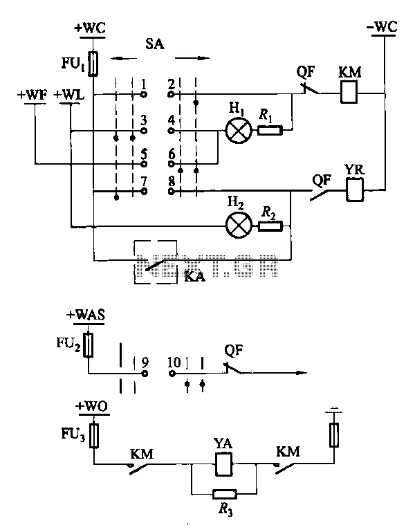
Factories and enterprises operating at voltages of 10 kV and below commonly utilize the CD10 (formerly CD2) type electromagnetic actuator as a circuit breaker. This mechanism features a mechanical anti-jump device. The control signal circuit for the CD10 actuator...
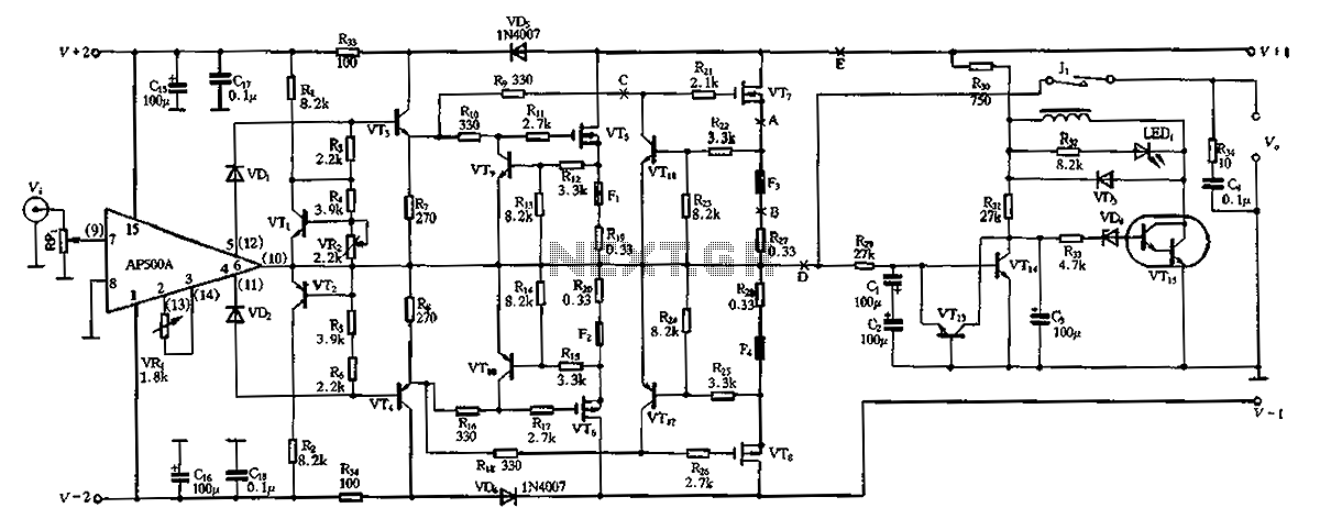
The CPI is a 100W DC super power amplifier circuit based on the AP500. It features a parallel push-pull amplifier output stage composed of transistors VT5, VT6, and VT7 to enhance output power. The circuit's output power is low...
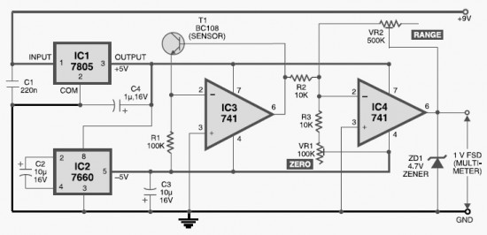
This DIY digital thermometer circuit can measure temperatures up to 150°C with an accuracy of ±1°C. The temperature is displayed on a 1V full scale deflection. The digital thermometer circuit is designed to provide accurate temperature readings within a specified...
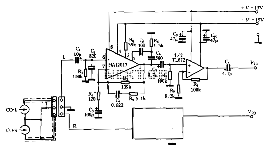
Figure 3-16 illustrates a low-noise preamplifier equalizing circuit using the HA12017. This circuit includes playback components R3, R4, and C4, which conform to a standard balanced network. The gain of the circuit is -7dB at 1kHz, while the output...
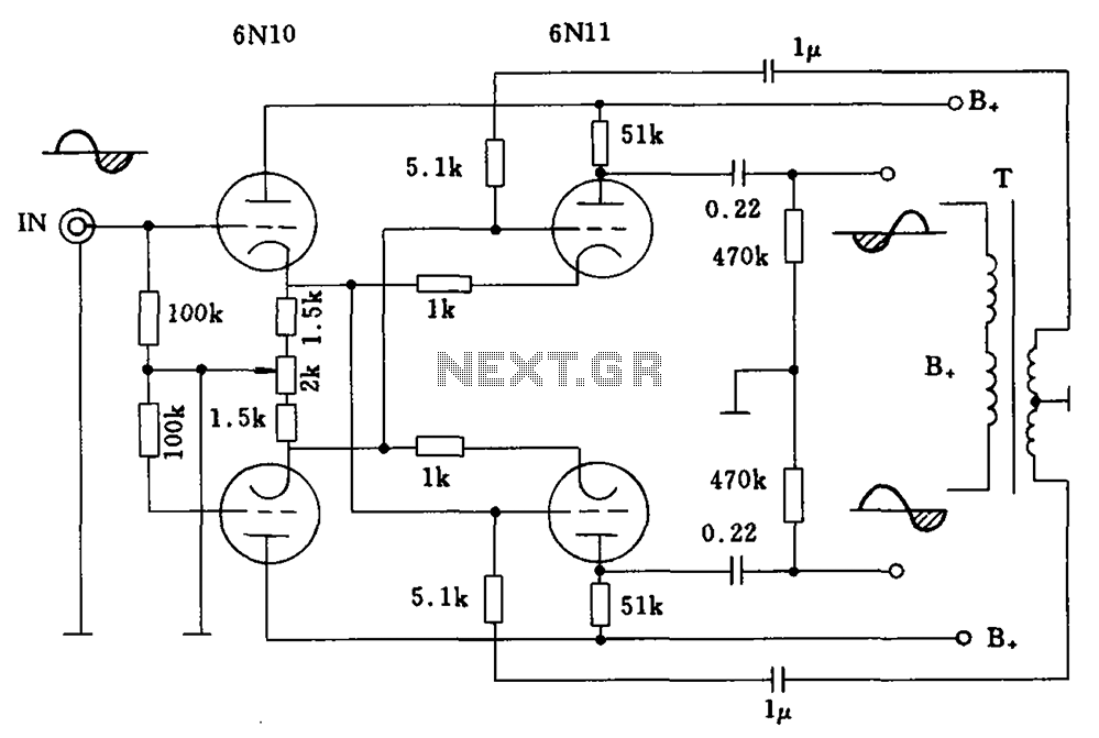
Balanced cross tube inverter circuit, also known as the Chelles inverter circuit, can be utilized as a preamplifier and employs 6N10 and 611 tubes in an inverted configuration. The circuit is designed to work with a final amplifier tube, specifically...