
Low-noise pre-equalizer circuit
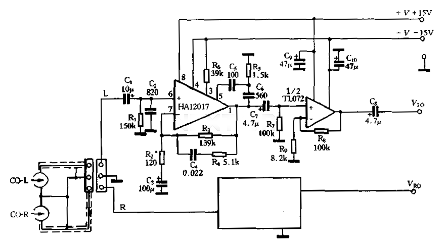
The low-noise preamplifier circuit depicted in Figure 3-16 is designed to enhance audio signals while minimizing unwanted noise. The HA12017 integrated circuit serves as the primary amplification component, ensuring high fidelity in audio playback. The inclusion of resistors R3 and R4, along with capacitor C4, establishes a balanced network configuration that optimizes the signal path and reduces interference.
The circuit's gain of -7dB at 1kHz indicates that it is configured to attenuate the input signal slightly, which is typical for certain preamplifier applications. However, the output signal level of 65.7 mV at 1kHz suggests that the circuit is capable of producing a usable signal for subsequent processing stages. The pre-equalizer output level of 27dB indicates that the circuit is not adequately amplifying the signal to meet the standard input requirements of a 10dB power amplifier, necessitating the addition of a secondary amplification stage.
To address the amplification deficiency, a voltage amplification stage with a gain of 20dB is recommended. This additional stage can be implemented using operational amplifiers such as the TL072, TL082, or NE5532, which are well-suited for audio applications due to their low noise characteristics and high slew rates. The choice of operational amplifier will depend on specific design requirements, including bandwidth, power supply voltage, and load conditions.
Furthermore, the versatility of the HA12017 allows it to be used in various audio applications beyond tape sound recording. By modifying the RC network, the circuit can be adapted for use in RIAA phono pre-equalizer configurations, which are essential for processing signals from vinyl records. This adaptability highlights the importance of selecting appropriate component values in the RC network to ensure proper frequency response and equalization tailored to the specific audio source.
Overall, the design of this low-noise preamplifier equalizing circuit demonstrates a comprehensive approach to audio signal processing, combining effective amplification with flexibility for various applications in the audio domain.Figure 3-16 is a low-noise preamplifier equalizing HA12017 consisting playback circuit, the circuit R3, R4 and C4, in line with standard maggots balanced network. The gain stag e circuit 38 - 7dB (1kFk), the head output signal is a 65,7 Pi (1kH), pre-equalizer circuit output level of a 27dBo which for most standard input level of a 10dB power amp circuit is not enough, so there is need to add a voltage level of the amplifier stage 20dB amplification capability to fill the gap. Put this big stage can TL072, TL082 and NE5532 to serve O HA12017 applies not only to pre-equalizer circuit tape sound recording, but also applies to the electromagnetic RIAA phono pre-equalizer circuit.
Then just change the RC network.
Related Circuits
A purchase was made of the EDE702 along with an LED-backlit LCD character display. After acquiring the EDE702, it was determined that it lacked sufficient integration with HD44780-compatible displays to justify its cost. However, utilizing it was preferable to...
The circuit operates by sending ringing pulses through capacitor C1, resistor R1, and diode D2 to charge capacitor C2 to a voltage of 6V. This voltage causes transistors N1 and N2 to reverse, which activates V1, the analog hook,...
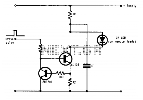
Q1 and Q2 form a constant current drive defined by R2. The current (I) approximates the reciprocal of R2 in the circuit shown for values of I greater than 1 amp. The pulse current is drawn from C1, which...
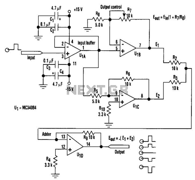
By adjusting one potentiometer, the output of this circuit can be varied from a positive version of the input signal, smoothly transitioning through zero output, and then to a negative version of the input. For instance, if the input...
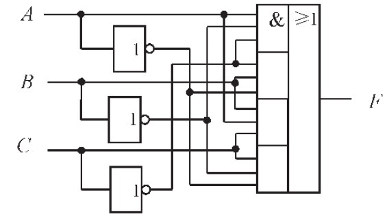
The design of the combinational logic circuit is diverse. An example chosen for detailed explanation is the implementation of an even parity check circuit. The parity check circuit exhibits particular characteristics and practicality in the analysis and design of...
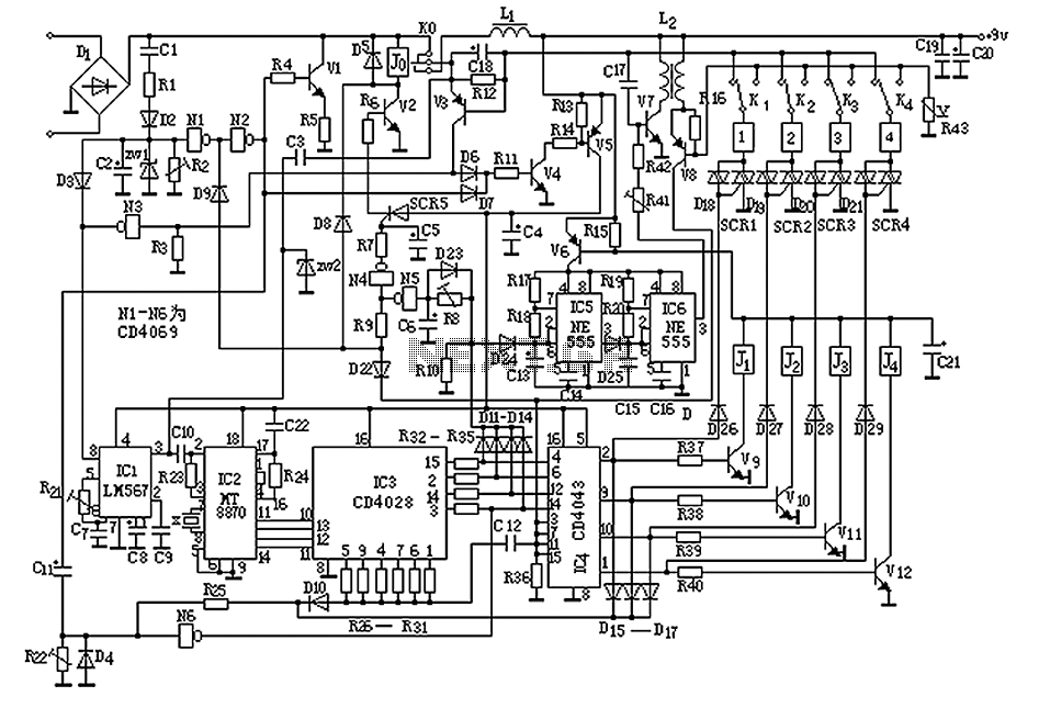
This circuit enables the switching on and off of appliances through telephone lines. It allows for the control of appliances from any distance, overcoming the limitations of infrared and radio remote controls. The circuit can manage up to nine...