
Balanced cross tube inverter circuit

The balanced cross tube inverter circuit is an essential component in audio amplification systems, particularly in high-fidelity applications. This circuit operates by converting a single-ended signal into a balanced output, which significantly reduces noise and distortion, leading to improved audio quality.
The 6N10 and 611 tubes serve as the active elements in the inverter stage, providing the necessary gain and phase inversion. The 6N10 is a dual triode that allows for efficient signal amplification, while the 611 tube, a power triode, is often used in audio applications for its warm sound characteristics and high output power capability.
The circuit typically features a differential input stage, allowing for the rejection of common-mode noise, which is crucial in maintaining signal integrity in audio systems. The output stage, utilizing the 300B tube, is known for its linearity and low distortion, making it an excellent choice for driving speakers in high-end audio setups.
Overall, the balanced cross tube inverter circuit is a sophisticated design that combines the unique properties of vacuum tubes with modern audio engineering principles, resulting in a highly effective amplification solution for audiophiles and professional sound engineers alike. Balanced cross tube inverter circuit is also known Chelles inverter circuit, it can be used as a preamp and 6N10,611 inverted. With the final amplifier tube amplifier using 300 B mating.
Related Circuits
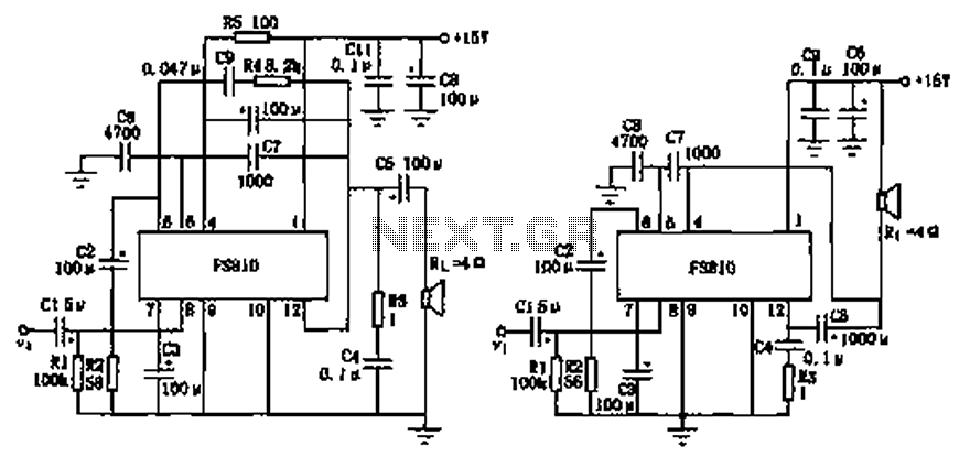
The FS810 circuit serves as a practical implementation of an integrated power amplifier. The FS810 is designed for high-performance use in high-end tape recorders and audio equipment. In the schematic, the speaker is connected to the output capacitor C5...
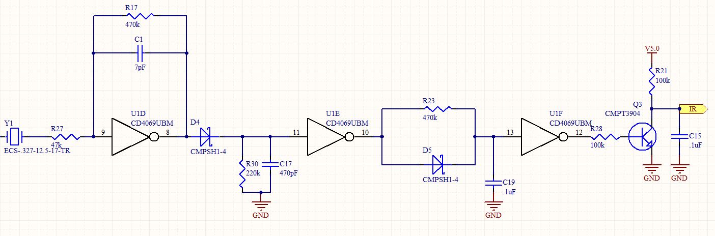
This is a follow-up to an earlier post regarding a specific circuit schematic. The circuit is designed to operate at a supply voltage of 5V, and testing has confirmed that the original device functions correctly at this voltage. A...

This circuit is a module for a diesel and horn train system. It is constructed using a 555 timer IC and several operational amplifiers (op-amps). The circuit serves as a complete system for the horn function. The main power...
Developed as an interface between the General Instruments AY-3-8500-1 TV game chip and the antenna terminal of a TV set. Adjust capacitor C1 to the frequency of an unused channel to which the receiver is set for playing games....
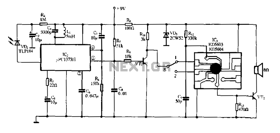
Electronic Miss Manners infrared receiver and voice circuits The Electronic Miss Manners system integrates an infrared (IR) receiver with voice circuits to facilitate communication and interaction. The IR receiver is designed to detect signals emitted from a remote control or...
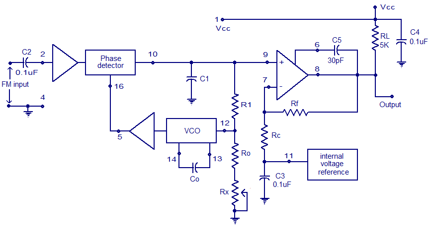
A simple PLL FM demodulator circuit using the IC XR2212 is presented. The XR2212 is a highly stable, monolithic PLL (phase-locked loop) IC specifically designed for communication and control system applications. It operates within a frequency range of 0.01...