
A four channel X/Y oscilloscope multiplexer
The multiplexer design is centered around the need for a versatile oscilloscope capable of handling complex simulations, particularly for systems like multiple spring-mass setups. The use of banana jacks on the front panel provides convenient access for standalone operation, while the 15-pole SUB-D connector on the rear facilitates integration into a larger analog computing setup. Each of the eight input channels (four for X and four for Y) is equipped with a ten-turn precision potentiometer, allowing for fine-tuning of signal levels before they are processed. This careful attenuation is crucial to maintain linear behavior and prevent signal distortion.
The operational amplifier stage following the potentiometers serves two purposes: it amplifies the input signals by a factor of 10 and adds a constant position signal to enable the shifting of figures on the display. By using high-quality OP27 operational amplifiers, the design ensures low noise and high precision in the signal processing chain.
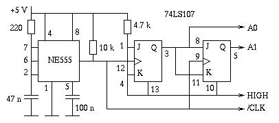
The MAX 355 dual 4:1 analog multiplexer is at the heart of the selection mechanism, governed by binary counter signals that determine which input channels are active at any given time. The output of the multiplexer feeds into two additional OP27 stages, which drive the X/Y inputs of the oscilloscope. A critical aspect of the design is the incorporation of blanking logic, which effectively eliminates any visual artifacts that might occur when switching between figures. This ensures a clean transition on the display, maintaining the integrity of the visual representation of the simulation.
The control panel is designed with user interaction in mind, featuring a four-position rotary switch that allows the operator to select the number of figures displayed concurrently. The blanking logic is engineered to ensure that the display intensity remains constant regardless of the number of displayed figures, enhancing usability and visual clarity. Additional controls include a power switch with dual LEDs indicating the status of the positive and negative power supplies, as well as a toggle switch to select between front and back panel inputs.
Overall, this multiplexer project exemplifies a sophisticated approach to expanding the capabilities of oscilloscopes, providing a powerful tool for engineers and researchers engaged in complex simulations and analyses. The extensive cabling and careful layout reflect the intricate nature of the design, ensuring that all components work harmoniously to deliver reliable performance in demanding applications.I have some Tektronix oscilloscopes with appropriate plug in units yielding an four channel display, I always wanted something else: A true four channel oscilloscope with four distinct X/Y inputs which would allow me not only to display four traces with a common X deflection but to draw up to four distinct figures on the screen at the sam e time. Something like this is very useful in conjunction with an analog computer, i. e. one can display different movong masses in a simulation at once, etc. This led to the development of such multichannel X/Y oscilloscopes like the truly wonderful Telefunken OMS 800 dual channel oscilloscope. Although I am the proud owner of such an instrument, its limitation to only two channels was a bit disappointing (currently I want to simulate a multiple spring-mass-system and display all moving masses at once to get a feeling for the forces of the system), so decided to build my own multiplexer.
The front plate of the instrument can be seen above - below is a picture taken during the calibration of the multiplexer (it is a bit blurry - sorry for the bad quality - I desperately need a camera fixture for my oscilloscopes) - four Lissajous figures displayed at once (it is always the same figure since, it is some kind of a proof of concept picture): The basic structure of the multiplexer is simple, although it was one of the more complex projects I implemented during the last years which is due to the fact of the excessive cabling necessary for all of the control elements on the front (and back) plate: There are four X and Y inputs on the front plate using banana jacks and on the back plate using a 15 pole SUB-D connector. Using a switch on the front plate one of these signal sources can be activated using two rather large relays (since this is not time critical and will be done only during startup, I preferred relays over semiconductor multiplexers here).
The front panel input jacks will be used for stand alone operation while the back panel input connector will be used when the multiplexer will become an integral part of a larger analog computer where the input lines will be tied to the central patch panel by appropriate trunk lines. Each of the eight inputs is fed to a ten turn precision potentiometer for input attenuation before being fed through an impedance converter to remove any load from the potentiometers, thus assuring a linear behaviour.
Following these converters the signals are fed through an additional operational amplifier stage with an amplification rate of 10 which is also used to add a constant position signal to allow the shifting of each of the four figures. Following these operational amplifier stages comes the multiplexer, a MAX 355 which is a dual 4:1 analog multiplexer.
This multiplexer receives to binary counter signals and feeds two output stages built from OP27 operational amplifiers driving the X/Y input lines of the oscilloscope connected to the multiplexer. The tricky part is the blanking logic since I did not want to see faint lines between the figures when the beam moves from drawing one figure to the next.
In addition to this the blanking logic allows the selection of one, two, three or four indepentent figures to be displayed simultaneously. 12 banana jacks (5 times ground, 4 times X, 4 times Y, 1 input to deactivate the oscilloscope output during halt and initial value times of the analog computer).
A four position rotary switch to select the number of individual channels to be displayed concurrently (the blanking logic guarantees that the intensity of the display will not change with the number of figures displayed!). The power switch with two power LEDs (one for the positive supply, one for the negative) and one switch to select between front panel input and back panel input.
The pictures above give an impression of the immense amount of cabling necessary to connect all of the front panel contro 🔗 External reference
Related Circuits
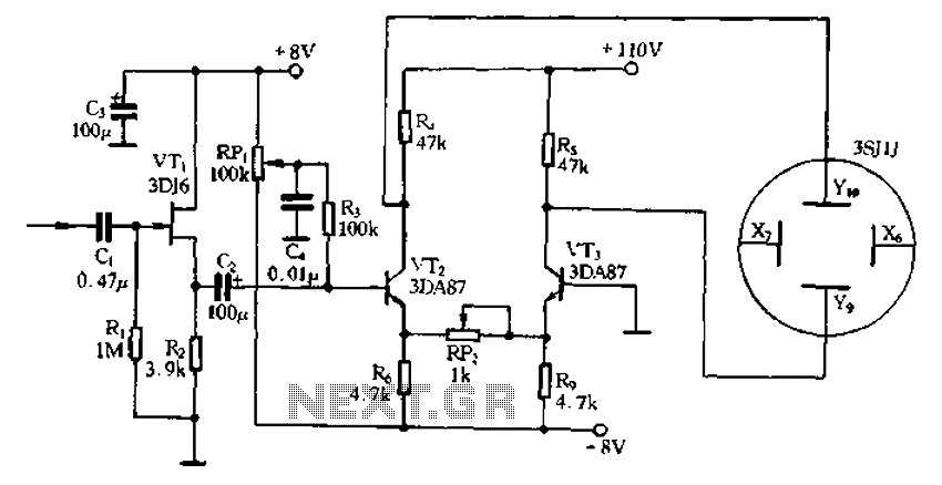
Application of the differential amplifier circuit in a simple small oscilloscope. The differential amplifier circuit is a crucial component in the design of a simple small oscilloscope. This circuit is designed to amplify the difference between two input voltage signals...
A 10 MHz crystal typically exhibits an impedance of 4 ohms at its series resonance and 40 kiloohms at its parallel resonance. To minimize sideband noise, the power dissipated in the crystal must be substantial; the design presented here...
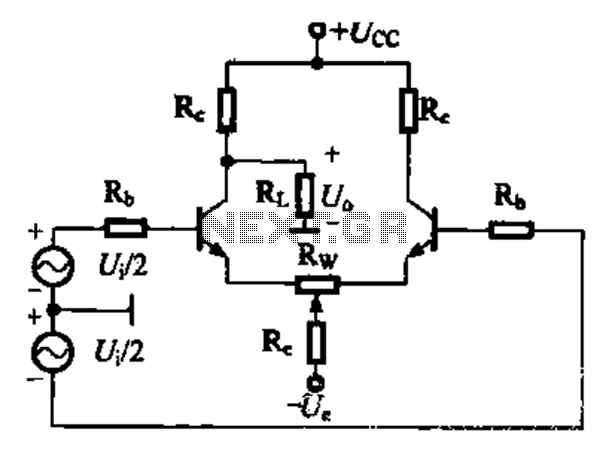
A comparison of four connection methods and features of a differential amplifier circuit is presented. The circuit demonstrates a magnification of a single tube with half the earnings, effectively countering common-mode negative feedback effects. The Common-Mode Rejection Ratio (CMRR)...
This reference design demonstrates the MAX98400 Class D audio amplifier in a stereo audio docking station application. The demo box is a powered speaker dock that drives a speaker system consisting of 2-inch satellite speakers and a 5-inch subwoofer. The...
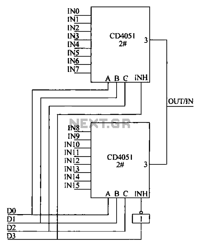
The CD4051 is a single-ended input 8-channel multiplexer that features three channel select inputs (A, B, C) and an inhibit input (INH). The signals at inputs A, B, and C are utilized to control the selection of one of...
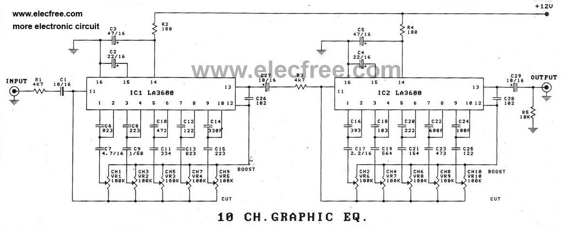
In addition to using the LA3600 IC, a 5-channel graphic equalizer can also be designed as a 10-channel graphic equalizer circuit through appropriate connections. The design of a 10-channel graphic equalizer circuit utilizing the LA3600 integrated circuit (IC) offers enhanced...