
xx Band Audio Equaliser
A 20-band equalizer (EQ) is designed to allow precise control over the frequency response of audio signals, particularly in high-power applications such as a 900-watt MOSFET power amplifier. The equalizer achieves this by dividing the audio spectrum into 20 discrete frequency bands, each of which can be adjusted independently to enhance or attenuate specific frequencies.
The operational principle of the EQ involves using band-pass filters for each frequency band. Each filter section typically comprises resistors, capacitors, and operational amplifiers (op-amps) configured to define the center frequency and bandwidth of the filter. The output level of the EQ is influenced by the resistors used in the circuit; specifically, when two equal resistors are employed, the gain can be set to 3, which means the output signal will be amplified to three times the input signal level, compensating for any losses incurred through the filtering process.
In the schematic, the filter sections are critical components that determine the EQ's performance. Each filter section can be constructed using a combination of passive components (resistors and capacitors) and active components (op-amps) to shape the frequency response. The design allows for flexibility; additional filter sections can be added to increase the number of frequency bands, thereby enhancing the equalization capabilities of the amplifier.
To clarify the filter section's role, it is essential to understand that each filter is tuned to a specific frequency. The selection of resistor and capacitor values dictates the cutoff frequencies and the gain characteristics of the filter. In essence, the filter section is responsible for isolating and adjusting the amplitude of a designated frequency band, which contributes to the overall sound shaping offered by the EQ.
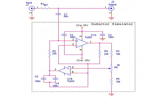
In conclusion, the design and implementation of a 20-band EQ for a high-power amplifier involve careful consideration of filter sections, gain settings, and the interaction between components to achieve the desired audio output. The ability to manipulate multiple frequency bands allows for a tailored audio experience, making it a valuable addition to any high-performance audio system.A 20 Band EQ for my 900Watt MOSFET Power Amplifier. The Output Level would drop by the Ammount of resistors, so for 2 Equal Resistors, I should amplify it by a gainof 3. Would that propably work Eek, that is very confusing. The first schematic is a simple EQ and the text says, you can add as many bands as you want, by adding filter sections.
But I don`t realy get, what part of the whole Circuit is the Filter section. 🔗 External reference
Related Circuits
The hum noise is produced by an electronic device with improper design. To address this issue, it is essential to identify the source of the hum. This involves checking the grounding, cabling, casing, and other factors that may contribute...
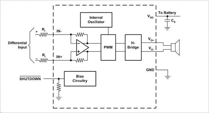
The EUA2123 is a highly efficient Class-D audio power amplifier capable of delivering up to 20W into a 4-ohm load in stereo mode using a single-ended (SE) configuration, or up to 40W into an 8-ohm load in mono mode...
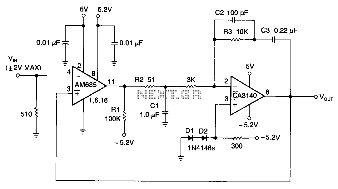
This circuit is capable of detecting positive peaks for signal frequencies exceeding 5 MHz, achieving an accuracy of ±1% for signal amplitudes ranging from 400 mV to 4 V peak-to-peak across sine, square, and triangular waveforms. The AM685 comparator...
The time constant of R1C1 determines the low cutoff frequency, while the time constant of R2C2 determines the high cutoff frequency. The pass-band gain, Avpass = R2/R1. For a high-pass filter, Za must be capacitors and Zb resistors. By...
A wideband RF detector is being designed, utilizing a series of resonant LC tanks spaced between 5 to 10 MHz apart, with an exception of 1 MHz spacing from 9 MHz onwards. The design of a wideband RF detector incorporating...
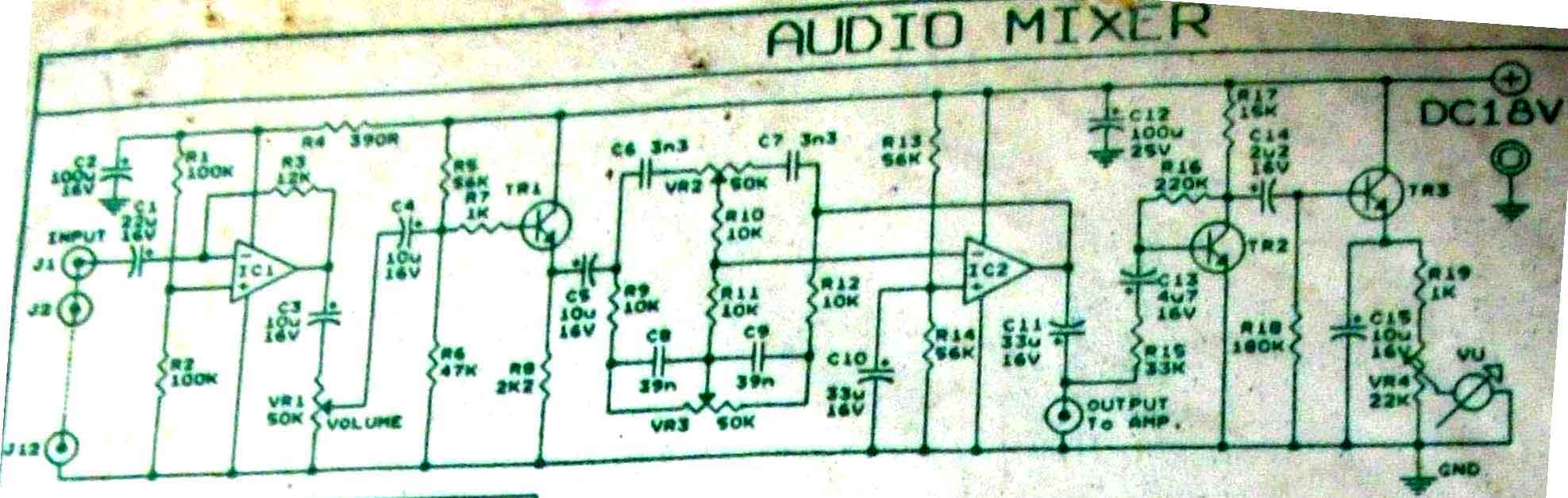
This is audio mixer circuit. The circuit is for one channel input, if you need, for example 5 channel mixer, then you need to build 5 similar circuits. The audio mixer circuit described is designed to handle a single channel...