
Commodore 64 Reset Logic

The U20 component operates as a 556 timer, which is a dual timer integrated circuit. In this configuration as a one-shot multivibrator, it generates a single output pulse in response to a triggering event. The pulse width is crucial for timing applications and is determined by the external resistor R34 and capacitor C24. The formula for calculating the pulse width indicates that the timing can be adjusted by changing the values of R34 and C24, allowing for flexible timing control in the circuit.
The output from pin 9 of U20 being "high" active means that when the timer is triggered, this pin will output a high voltage level for the duration of the pulse width, which can be utilized to activate other components in the circuit. Conversely, the output from U8 being "low" active indicates that it will output a low voltage level to signify a specific condition or state in the circuit.
The reset function plays a critical role in initializing the processor. Upon powering the device, the reset pulse is generated, which clears the processor's state and prepares it for operation. The program counter register is loaded with the starting address of the KERNAL, which is essential for the computer to begin executing the operating system. The addresses $FFFC and $FFFD are specifically designated for storing this starting address, ensuring that the processor knows where to begin its execution sequence. The KERNAL then takes control of the computer operations, managing various tasks and resources as needed. This initialization sequence is fundamental for the proper functioning of the computer system.U20 is a 556 timer configured as a one shot multivibrator. The output pulse width is determined by the size of R34 and C24. Pulse width = 1. 1 x R34 x C24 =. 5 seconds. The output on pin 9 is "high" active. The output of U8 is "low" active. Reset initializes all the processor logic and causes the processor to load the program counter register withthe address of the first instruction of the operating system program called the KERNAL. The starting address is stored in locations $FFFC and $FFFD. The first instruction is decode and executed giving KERNAL control of the computer operations. The reset pulse occurs when turning the power on to the computer. 🔗 External reference
Related Circuits
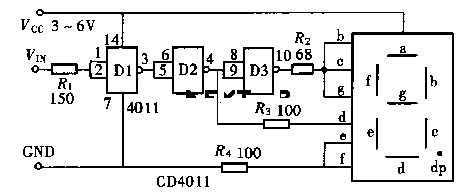
The door circuit logic pen text display can take many forms, utilizing various logic gates such as inverters, NAND gates, NOR gates, and others. A logical pen, exemplified by the NAND gate CD4011, can be used in conjunction with...
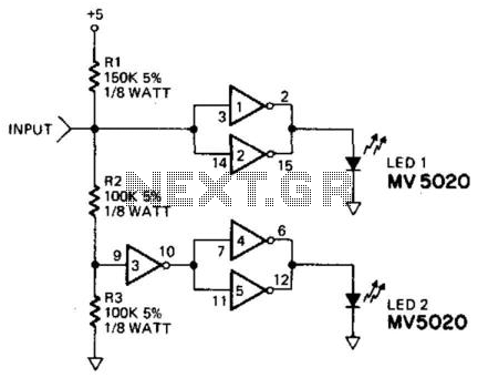
This logic probe utilizes a CD4009 CMOS hex inverter. The high-input impedance characteristic of CMOS technology prevents loading of the circuit under test. Since the output of the inverters is not defined at either a high or low level...

The circuit presented utilizes NAND logic gates from the Hitachi HD series, specifically the HD74LS00, which is a quad NAND integrated circuit. A special technique has been implemented to achieve three-state operation using a single IC. Gate N1 is...
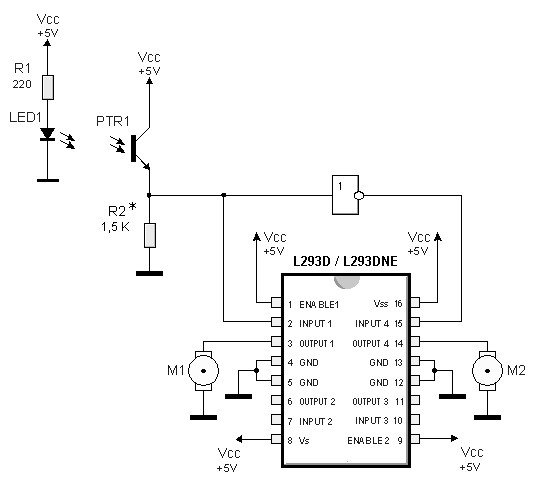
By utilizing logic chips, the behavior of a robot can be enhanced, allowing for the implementation of more complex algorithms. Logic chips, also known as logic gates or digital logic integrated circuits, are fundamental components in digital electronics that perform...
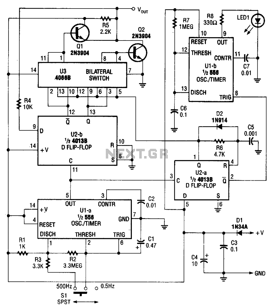
The pulser generates pulses at a user-selected frequency of 0.5 or 500 Hz, with a pulse width of about 5 ms. If the input to be pulsed is already being driven high or low by another output, the pulser...
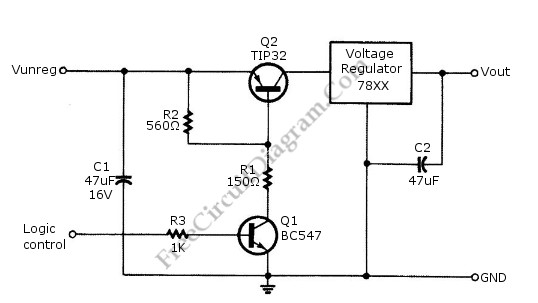
Logic power control of an analog regulator can be useful in applications where a digital circuit or controller needs to manage a power source, such as in EEPROM programmers or other power control systems. This circuit provides ON-OFF control...