
Cmos logic probe
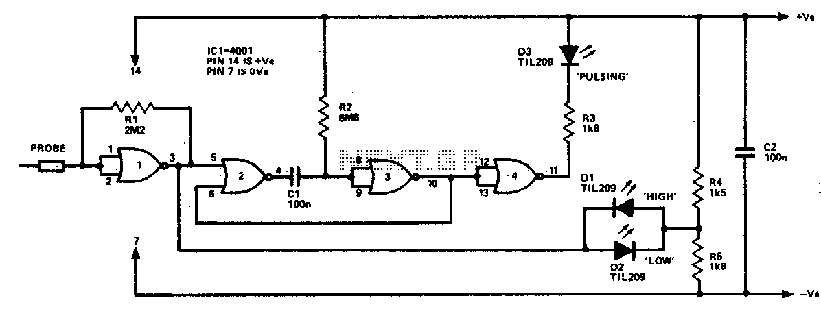
The logic probe is a diagnostic tool used for analyzing digital signals in electronic circuits. It is equipped with multiple LEDs that visually indicate the state of the input signal. The probe can detect four distinct states of the input signal, which are crucial for troubleshooting and verifying circuit functionality.
1. **Floating Input**: When the input is floating, meaning it is not connected to a defined voltage level, all LEDs remain off. This state indicates that there is no signal present, allowing the user to identify unconnected or improperly terminated lines.
2. **Logic 0 Input**: When the input signal is at logic level 0 (typically 0 volts), LED D2 is illuminated, indicating a low state. Additionally, LED D3 may briefly flash, suggesting that there may be transient signals or noise present in the circuit that could be influencing the reading. This feature helps in diagnosing issues related to signal integrity.
3. **Logic 1 Input**: In the case of a logic level 1 (typically a higher voltage, such as 5 volts), LED D1 lights up. This clear indication allows the user to confirm that the input is receiving a strong high signal, which is essential for proper operation in digital circuits.
4. **Pulsing Input**: If the input signal is pulsing, LED D3 will activate, indicating that the signal is fluctuating between high and low states. In scenarios where the input signal is of low frequency, one or both of the other indicators (D1 or D2) may also illuminate, providing insight into the predominant state of the input. This feature is particularly useful for observing clock signals or other periodic waveforms.
The design of the logic probe allows for easy interpretation of digital signals, making it an invaluable tool for engineers and technicians in diagnosing and analyzing digital circuits. Its ability to provide real-time feedback on the state of an input signal enhances troubleshooting efficiency and aids in the verification of circuit designs.The logic probe can indicate four input states, as follows: floating input—all LEDs off logic 0 input—D2 switched on (D3 will briefly flash on); logic 1 input—Dl_ switched on; pulsing input—D3 switched on, or pulsing in the case of a low frequency input signal (one or both of the other indicators will switch on, showing if one input state predominates). 🔗 External reference
Related Circuits
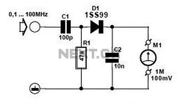
Comprehensive information about RF Probe Circuits is available. Users can learn about and download RF Probe Circuit designs online. RF Probe Circuits are essential tools for testing and analyzing radio frequency signals in various applications, including telecommunications, broadcasting, and electronic...
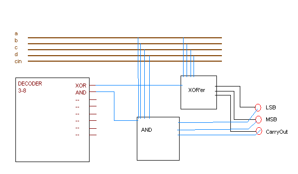
A 2-bit ALU is being created with eight defined functions, which are identified by a 3-bit code. These functions include operations such as AND and XOR, and they operate on two 2-bit binary numbers to produce a 2-bit output....
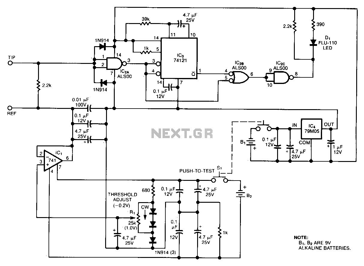
Oscilloscope measurements of ground noise can be unreliable because noise can enter your circuit via the scope's three-pronged power plug. This issue can be mitigated by utilizing the ground-noise tester described. The circuit operates on two 9-V batteries and...
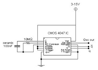
This circuit generates a digital square wave that can be displayed directly or utilized to drive additional circuits. It employs the CMOS 4047 Low-Power Monostable/Astable Multivibrator, as referenced in Tom Duncan's "Adventures with Digital Electronics" book, to control a...
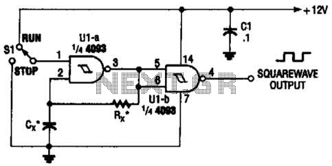
Two gates of the Quad 4093 are utilized to create an oscillator. The resistor (R) can range from approximately 5 kΩ to around 10 kΩ. The capacitor (Cx) can vary from about 10 pF to higher values, with the...
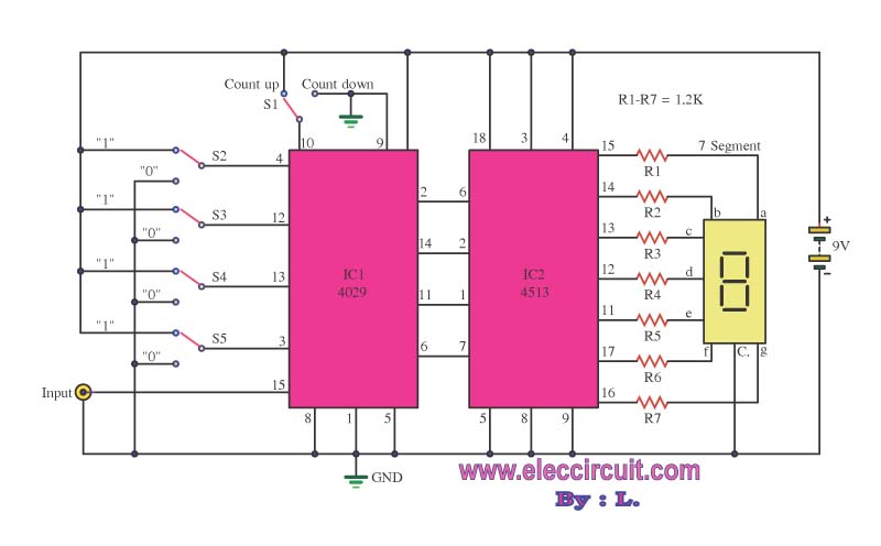
This is a simple digital counter circuit utilizing the IC 4029 to process binary data, which is then sent to the IC 4513, a driver IC for a 7-segment display to show the output. The digital counter circuit is designed...
Warning: include(partials/cookie-banner.php): Failed to open stream: Permission denied in /var/www/html/nextgr/view-circuit.php on line 713
Warning: include(): Failed opening 'partials/cookie-banner.php' for inclusion (include_path='.:/usr/share/php') in /var/www/html/nextgr/view-circuit.php on line 713