
Capacitive proximity sensor detection circuit
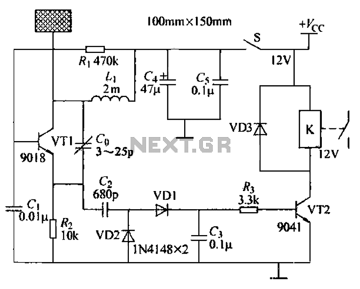
The capacitive proximity controller operates on the principle of detecting changes in capacitance caused by nearby conductive objects. The core of the circuit is the radio frequency (RF) oscillation circuit, which utilizes the transistor VT1 as an active component. The oscillation frequency is determined by the values of the inductor L1 and the capacitor G. When the system is powered, the oscillation circuit generates an RF signal that is transmitted through the sensor electrode.
As a conductive object approaches the sensor, it alters the electric field around the sensing electrode, effectively increasing the capacitance between the electrode and the ground. This change in capacitance results in a decrease in the positive feedback necessary for the oscillator to maintain its oscillation. The decrease in feedback leads to a reduction in the amplitude of the RF signal, and eventually, the oscillator may stop oscillating altogether.
The output of the RF detector circuit is a DC control signal that is used to control the state of the relay. When the oscillator is operating normally, the control signal keeps the relay energized, allowing current to flow to the connected load. Conversely, when the oscillator stops due to the presence of a nearby conductor, the control signal drops, causing the relay to de-energize and disconnect the load.
The sensitivity of the proximity sensor can be fine-tuned by adjusting capacitor G. This adjustment allows for the calibration of the detection distance and the size of the objects that can be detected. The inductor L1's value plays a crucial role in determining the overall performance of the circuit; hence, careful selection of its inductance is necessary to ensure optimal operation. If an inductor value greater than 4 mH is used, it is essential to increase the capacitance of G to accommodate the changes in circuit dynamics and maintain stable oscillation characteristics.
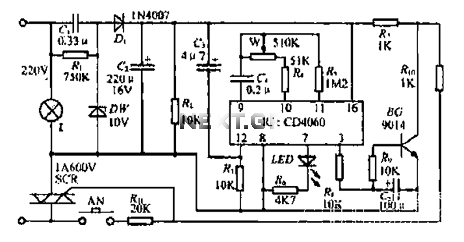
In summary, the capacitive proximity controller is a versatile and effective circuit for detecting the presence of conductive objects through capacitance changes, with adjustable parameters to suit various applications. Capacitive proximity controller usually consists of a radio frequency oscillation circuit and a detection plate. Figure 6-56 is produced with discrete components capacitive pro ximity sensing detection circuit. In the figure, the transistor VT1 to surrounding parts constituting a radio frequency oscillation circuit connected to the sensor electrode metal} VT1 of the collector electrode as a detector. In the absence of other conductors near the sensing electrode, the oscillator circuit composed of a normal oscillation VT1, VT1 this time send emitter voltage RF signal by VD1, VD2 after detecting a DC control signal which enables the switch VTZ wine guide, relay energized electrical pull, turn the power of the controlled circuit; when the conductive base near the sensing electrode sheet, for any conductor near the sensing electrode are induced bun capacitor electrode sheet and the land between the capacitor the increase will reduce the amount of positive feedback oscillator until the oscillator stops vibrating swing.
If stops the oscillator, the output RF detector circuit is no longer linear flow control signal, then it will switch off VT. So that the relay is de-energized, and the relay switch S Disconnect the need to release after re-closed, the oscillation circuit in order to enter the next state, otherwise relay Electric has been disconnected.
G is the sensitivity adjusting capacitor, adjust its size can be adjusted oscillator start-up, the threshold stop vibration, thereby to adjust the controller to control the object distance and size of the project. In Figure 6-56, the inductance of the inductor L1 can be used as 1-6mH any color code inductance, if the inductance greater than 4mH, it is necessary to appropriately increase the value of G, in order to enable a smooth start-up circuit,
Related Circuits
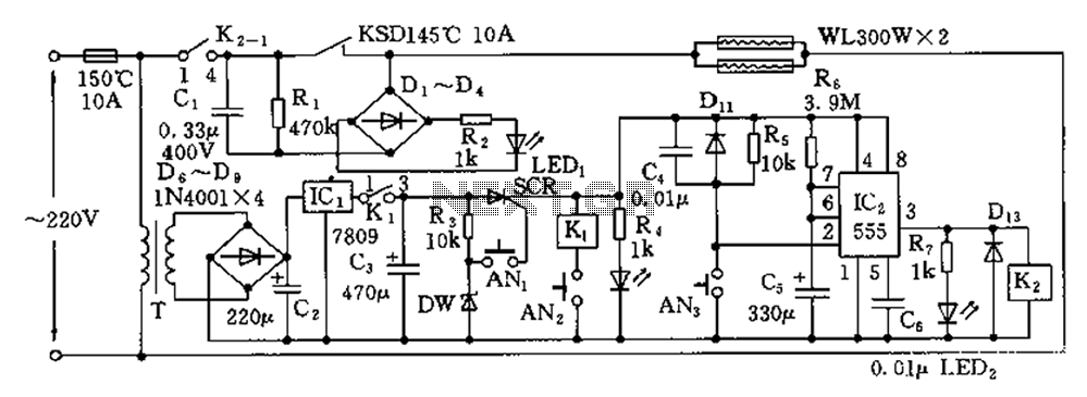
The disinfection cabinet circuit operates on the principle of using infrared heating within a closed cabinet to create a high-temperature environment for disinfecting tableware. The circuit includes an AC buck regulator, an infrared heating circuit, and a timing control...
The first BC109C transistor (on the left side) functions as a buffer, offering the circuit a high input impedance of approximately 250k ohms and a voltage gain slightly less than unity. As the Baxandall tone control circuit is a...

This is a design circuit diagram of a moderate power FM transmitter circuit. The circuit operates using two transistors. It consists of a complete circuit diagram. The operation of this circuit is explained as follows: the voice signals picked...

The PGA202 offset voltage correction circuit is designed to correct both input and output offset voltages. There are four different gain settings for the PGA202, which result in slight variations in input offset voltage. A 50k potentiometer is used...
Integrated circuit gates IC1-a and IC1-b form a monostable multivibrator, whose time constant is determined by capacitor C2 and resistor R3. When the transmitter is dekeyed and then almost immediately rekeyed, point TX+ goes low, causing pin 1 to...
The circuit includes a CD4 component with a connection of 16 feet for the Vcc terminal, 8 feet for the ground, 12 feet for the reset terminal, 7 feet for the Qt end, and 3 feet for the Q...
Warning: include(partials/cookie-banner.php): Failed to open stream: Permission denied in /var/www/html/nextgr/view-circuit.php on line 713
Warning: include(): Failed opening 'partials/cookie-banner.php' for inclusion (include_path='.:/usr/share/php') in /var/www/html/nextgr/view-circuit.php on line 713