
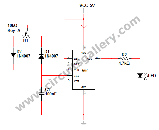
4017 For Flip-Flop Timer
The 4017 CMOS decade counter is a versatile integrated circuit that can count from 0 to 10, providing an output high on one of its ten output pins for each clock pulse received. In the context of a timer circuit, it can be used to generate timed intervals based on the charging and discharging of a capacitor.
The circuit operates by using a push-button switch (S1) to initiate the timing sequence. When the button is pressed, it allows capacitor C1 to discharge through resistor R2, which sets up the conditions for the timer. The discharge time of the capacitor, determined by the values of C1 and R2, can be calculated using the formula T = R2 * C1, where T is the time constant. This time constant defines how long it will take for the capacitor to discharge to approximately 37% of its initial voltage.
Once the capacitor discharges sufficiently, it triggers the clock input of the 4017 counter. The counter then advances its output state with each clock pulse, allowing for sequential activation of the output pins. The outputs can be connected to various devices or indicators, such as LEDs, to visually represent the counting process.
Additional components may be integrated into the circuit for enhanced functionality, such as diodes for preventing backflow of current, or additional resistors and capacitors to adjust timing characteristics. Proper grounding and power supply connections are also essential for stable operation of the circuit. The design can be further modified to include features like reset functionality or adjustable timing intervals, depending on the specific application requirements.
Overall, this circuit exemplifies a simple yet effective method to create a timer using a CMOS decade counter, leveraging basic electronic components to achieve desired timing functions.In this circuit 4017 CMOS decade counter can be used to build a timer circuit. Push-button S1 will discharge capacitor C1 through resistor R2 .. 🔗 External reference
Related Circuits
The following circuit illustrates a Cat and Dog Repellent Timer Circuit Diagram. Features include a high-output ultrasonic transmitter and the use of a standard 555 timer. The Cat and Dog Repellent Timer Circuit is designed to emit high-frequency ultrasonic sound...
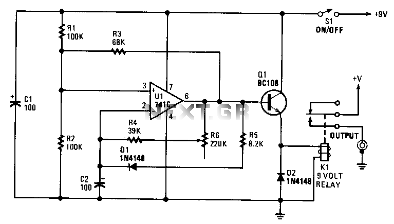
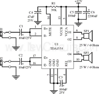
The interval can be set between approximately 5 to 30 seconds. A relay controls the slide-change mechanism. Operational amplifier U1 functions as a type of Schmitt trigger. Resistors R1 and R2 bias the non-inverting input at pin 3 of...
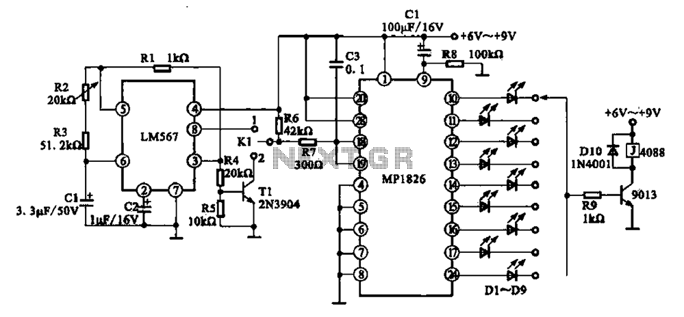
A precision circuit utilizing the LM567 timer, specifically the MPI826, where the LM567 functions as a dual-band oscillator. The MP1826 serves as a divider in the circuit, allowing the output signal from the LM567 to achieve extended timing. The...
A very long time constant is provided by R1 and C1. C1 discharges, and the near-zero voltage at its positive lead is applied to the high-impedance inputs of the circuit. In this circuit, the combination of resistor R1 and capacitor...
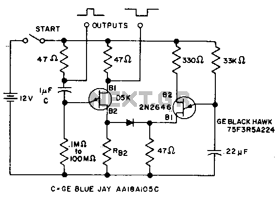
The timer interval begins when power is supplied to the circuit and ends when voltage is applied to the load. The 2N2646 transistor is utilized in the oscillator, which generates pulses to the base of the D5K. This configuration...
How to change the brightness of an LED. Are LED lights dimmable? Is it possible to adjust the brightness of LEDs? An LED is essentially a diode; when the forward voltage exceeds 0.7 volts, it begins to emit light,...
Warning: include(partials/cookie-banner.php): Failed to open stream: Permission denied in /var/www/html/nextgr/view-circuit.php on line 713
Warning: include(): Failed opening 'partials/cookie-banner.php' for inclusion (include_path='.:/usr/share/php') in /var/www/html/nextgr/view-circuit.php on line 713