
Cat And Dog Repellent Timer
The Cat and Dog Repellent Timer Circuit is designed to emit high-frequency ultrasonic sound waves that are unpleasant to cats and dogs, effectively deterring them from entering certain areas. The core of this circuit utilizes a 555 timer IC, which operates in astable mode, generating a continuous square wave output. This output is fed into an ultrasonic transmitter, which converts the electrical signal into sound waves.
The circuit typically consists of several key components: a 555 timer IC, resistors, capacitors, a transistor for amplifying the signal, and the ultrasonic transducer itself. The resistors and capacitors connected to the 555 timer determine the frequency of the output signal, which is generally set between 20 kHz and 25 kHz, a range that is inaudible to humans but can be heard by animals.
The ultrasonic transducer is responsible for converting the electrical signal from the timer into ultrasonic sound waves. The output from the 555 timer is usually insufficient to drive the transducer directly, so a transistor is employed to amplify the signal. This amplification ensures that the ultrasonic waves produced are strong enough to be effective in repelling animals.
The circuit can be powered by a standard DC power supply, and it may include features such as an adjustable timer to control how long the ultrasonic sound is emitted. Additionally, it can be designed to operate intermittently, thereby conserving power and prolonging the life of the device.
This circuit is particularly useful for homeowners looking to protect their gardens or outdoor spaces from unwanted animal intrusions without causing harm to the animals. The simplicity of the design allows for easy assembly and customization, making it accessible for hobbyists and professionals alike.The following circuit shows about Cat And Dog Repellent Timer Circuit Diagram. Features: high output ultrasonic transmitter, uses a standard 555 .. 🔗 External reference
Related Circuits
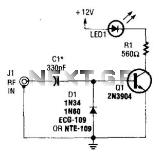
A simple RF detector circuit utilizing a visual indicator can serve as an RF output indicator. This circuit was designed for use as a transmitter ON indicator. The RF detector circuit typically consists of a few key components: a diode,...

During the recent audio hackers meetup at Hacker Dojo, discussions were held with Laura and Kevin regarding the challenges faced in creating a small local network referred to as "JamLan." There was mention of the consideration to develop a...
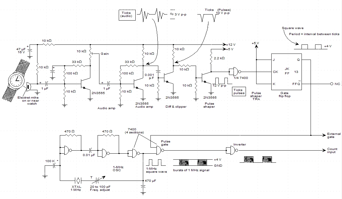
A schematic for a watch timer was found in a hobby electronics book. The circuit adapts a frequency counter to measure intervals. Watch ticks are clipped, shaped, and formed into a square wave. This square wave is utilized to...
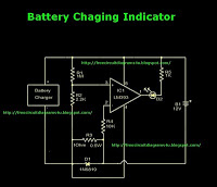
This is a battery charger indicator circuit diagram. When the battery is charging, it is indicated by an LED. This circuit can be used with a 12V battery with a charging current of less than 1A. The battery charger indicator...
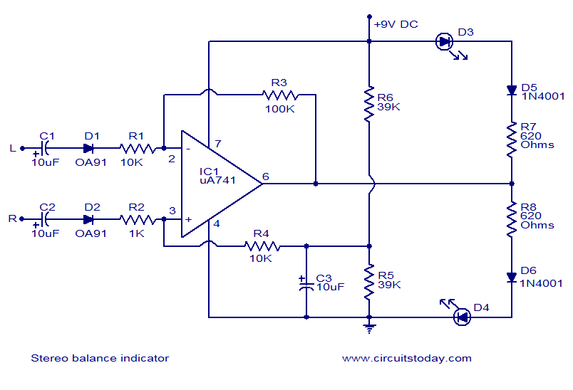
This is one of the simplest stereo balance indicator circuits available. The circuit provides a visual indication using two LEDs, which represent the difference in balance between the left and right channels of a stereo system. It is based...
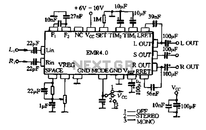
The EMR 4.0 operates with a single power supply ranging from 6V to 10V, with an optimal supply voltage of 9V. It requires effective power filtering to minimize noise, particularly when there is no signal input. The quiescent current...
Warning: include(partials/cookie-banner.php): Failed to open stream: Permission denied in /var/www/html/nextgr/view-circuit.php on line 713
Warning: include(): Failed opening 'partials/cookie-banner.php' for inclusion (include_path='.:/usr/share/php') in /var/www/html/nextgr/view-circuit.php on line 713