
CMOS 4011 Long Delay Timer
In this circuit, the combination of resistor R1 and capacitor C1 creates a time constant that significantly influences the circuit's response to changes in input voltage. The time constant, denoted by τ (tau), is calculated as τ = R1 * C1, where R1 is the resistance in ohms and C1 is the capacitance in farads. This relationship indicates how quickly the capacitor C1 charges and discharges, ultimately affecting the voltage levels at the circuit's output.
When C1 discharges, it does so slowly due to the high resistance value of R1, resulting in a gradual decrease in voltage at the positive lead of the capacitor. This near-zero voltage is crucial for high-impedance inputs, as it minimizes the loading effect on the preceding stages of the circuit. High-impedance inputs are designed to draw minimal current, thus ensuring that the voltage levels remain stable and unaffected by the input stage.
The long time constant provided by R1 and C1 is particularly useful in applications such as analog signal processing, filtering, and timing circuits, where precise voltage levels and timing characteristics are essential. In these scenarios, the circuit can effectively integrate signals over time, allowing for smooth transitions and reducing noise. Furthermore, the choice of R1 and C1 values can be adjusted to tailor the time constant to meet specific design requirements, enabling the circuit to respond appropriately to various signal conditions.A very long time constant is provided by R1 and C1. C1 discharges and the near zero voltage at its positive lead is applied to the high impedance inputs of the.. 🔗 External reference
Related Circuits
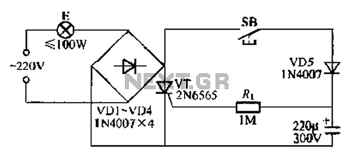
This circuit is a simple connection delay lamp circuit. When the lights are turned on and the switch is pressed, the power supply is activated. The capacitor charges rapidly, causing the thyristor (VT) to open, which in turn lights...
In counter mode, it provides 1 Hz resolution up to 100 MHz. In timer mode, the maximum resolution is 0.0000001 Hz up to 1 Hz. The resolution decreases by one digit for each additional decade. Multiple frequency updates per...
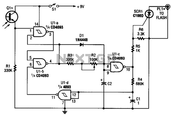
The circuit is built around a single 4093 quad 2-input NAND Schmitt trigger. Two gates from that quad package (U1-a and U1-b) are configured as a set-reset flip-flop. The 4093 integrated circuit (IC) contains four independent 2-input NAND gates with...
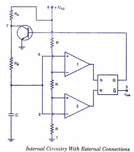
The 555 timer is a highly versatile integrated circuit that can be utilized to construct a wide variety of circuits. It can be effectively used without a detailed understanding of the function of each pin. The 555 timer is commonly...
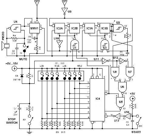
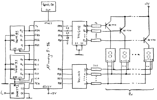
The time interval of this circuit can be varied digitally through the DIP switches. The time code must be set in BCD form. A 120 Hz signal generated by doubling the line frequency is used as the time reference....
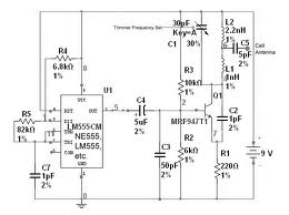
The team is highly interested in the design of a jammer circuit and has begun working on it. However, they are experiencing issues with the circuit, specifically that the signal is not being jammed effectively. The design of a jammer...
Warning: include(partials/cookie-banner.php): Failed to open stream: Permission denied in /var/www/html/nextgr/view-circuit.php on line 713
Warning: include(): Failed opening 'partials/cookie-banner.php' for inclusion (include_path='.:/usr/share/php') in /var/www/html/nextgr/view-circuit.php on line 713