
4017 IC For Three Hour Timer
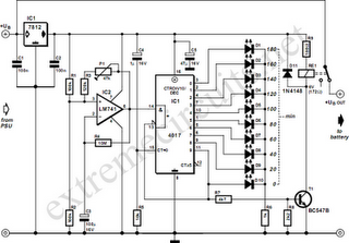
The circuit utilizes the 4017 decade counter IC to control the charging process. The 4017 IC is capable of counting pulses and can be configured to generate a specific output after a predetermined time interval. In this application, it is employed to manage the charging duration of a battery, ensuring that it is charged for exactly three hours.
The setup involves connecting the 4017 IC to a clock source, which can be derived from a timer circuit or an oscillator. The output from the 4017 IC can be connected to a relay or a transistor switch that controls the connection between the battery and the charger. When the circuit is powered on, the 4017 counts up to the set limit, which corresponds to the desired charging time. Upon reaching the count that signifies three hours, the output pin triggers the relay or transistor, effectively disconnecting the battery from the charger to prevent overcharging.
Additional components may include resistors and capacitors to stabilize the circuit and ensure accurate timing. A power supply is also necessary to provide the required voltage to the 4017 IC and other components. This arrangement allows for efficient battery management, promoting battery longevity and safety by preventing excessive charging.Function: made for battery charging time of three hours. Once the charging time is up the battery will be disconnected from the charger. Component: 4017 IC, .. 🔗 External reference
Related Circuits
This circuit deactivates an amplifier or other devices when a low-level audio signal at its input is absent for at least 15 minutes. By pressing P1, the device is activated, supplying power to any appliance connected to SK1. The...
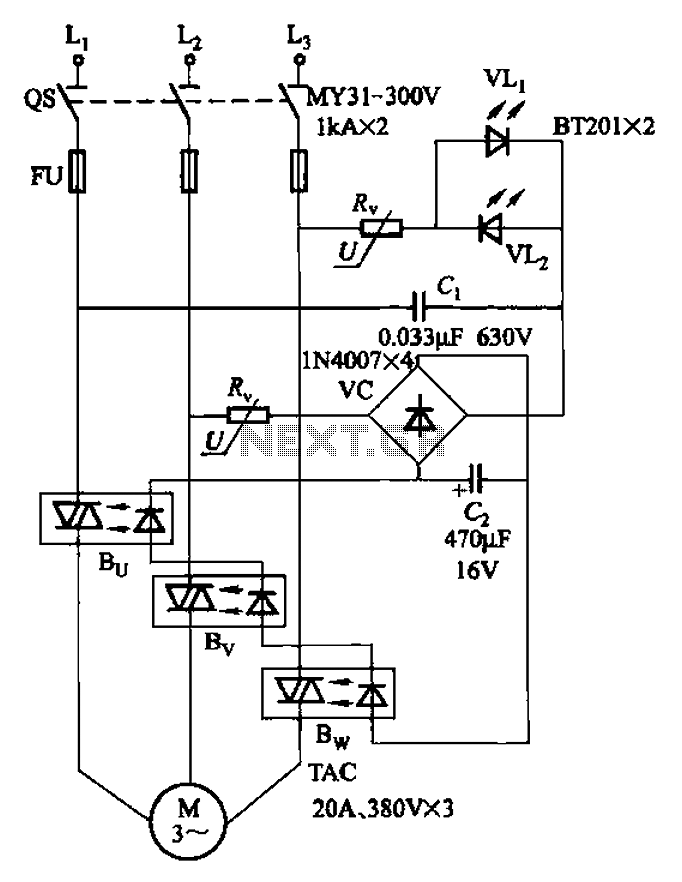
The circuit depicted in Figure 3-93 is integrated with an optical phase sequence protection relay. The circuit in question is designed to provide phase sequence protection using an optical relay mechanism. Optical phase sequence protection relays are crucial in applications...
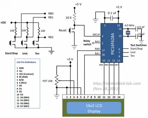
A source code for a simple PIC-based digital timer is provided. The hardware for the project is not available; however, it will be demonstrated using a DIY PIC16F628A breadboard module and I/O board. The complete circuit diagram and firmware...
The cumulative timer circuit comprises resistor R1 and an internal crystal oscillator, represented in a chart. Resistors R1 and R2 are metal film types, while resistors R3 to R5 are rated at 1/8W and also of the metal film...
The objective of this circuit is to power a lamp or other device for a predetermined duration (30 minutes in this instance) and subsequently turn it off. This functionality is particularly beneficial for reading in bed at night, as...
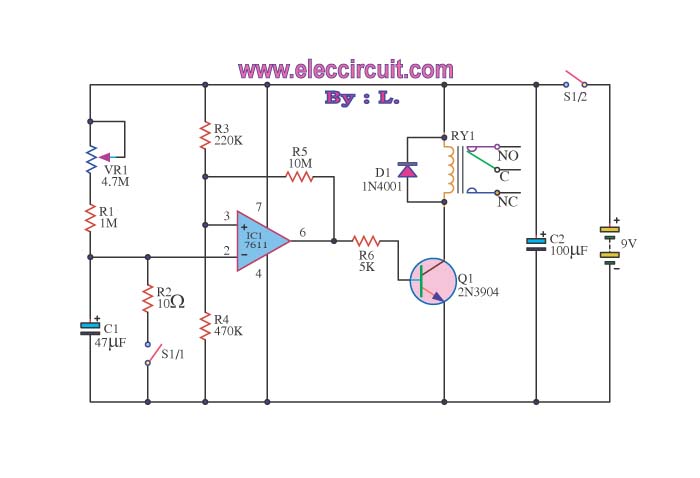
When switch S1/2 is activated, it powers the circuit C1, which utilizes the UA741 operational amplifier for voltage comparison. Pin 3 serves as the non-inverting input, while pin 2 is the inverting input. The voltage at pin 3 is...