
4017 LED Knight Rider
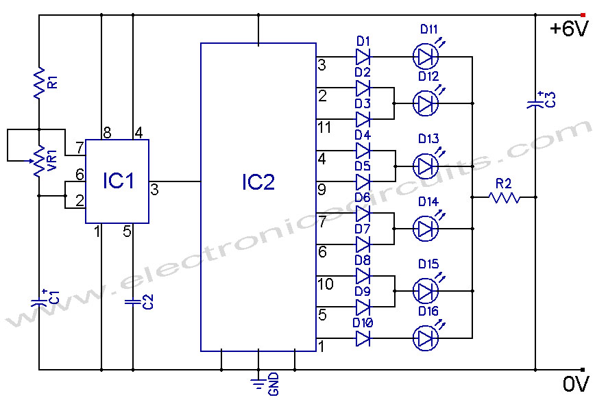
The 4017 LED Knight Rider circuit utilizes a 555 timer IC configured in astable mode to generate a continuous square wave output. This output serves as the clock signal for the CD4017 decade counter, which sequentially activates a series of LEDs, creating the characteristic "running light" effect reminiscent of the iconic Knight Rider television show.
In the circuit, the 555 timer's frequency can be adjusted by changing the values of the resistors and capacitors connected to it. The output from the timer triggers the CD4017, which has ten outputs corresponding to its ten counting states. Each output turns on an LED in succession, while the previous LED turns off, resulting in a visual effect where the lights appear to "run" back and forth.
The circuit can be powered by a DC power supply, typically ranging from 5V to 15V, depending on the specifications of the components used. It is important to ensure that the current-limiting resistors for the LEDs are appropriately calculated to prevent damage to the LEDs. The design can be further enhanced by adding additional features, such as adjustable speed control or the integration of more LEDs to create a more complex light pattern.
Overall, this circuit is an excellent demonstration of basic electronic principles, combining timing, counting, and visual output in a simple yet engaging manner.4017 LED Knight Rider Running Light Circuit Diagram In this 4017 Knight Rider circuit, the 555 is wired as an oscillator. It can be adjusted to give.. 🔗 External reference
Related Circuits

The BQ2000 is a programmable, monolithic integrated circuit designed for fast-charge management of nickel cadmium (NiCd), nickel metal-hydride (NiMH), or lithium-ion (Li-Ion) batteries in single or multi-chemistry applications. The BQ2000 detects the battery chemistry and employs optimal charging and...
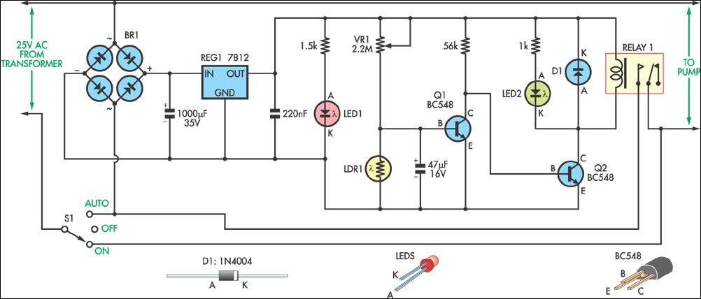
This circuit was designed to automatically control a garden pond pump, turning it on at dawn and off at dusk. This automation eliminates the need for manual operation, particularly beneficial during holidays when the owners are away. The controller...
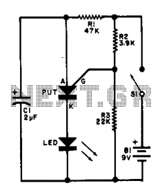
This flasher circuit functions as a relaxation oscillator, with capacitor C1 discharging periodically through the LED when the Programmable Unijunction Transistor (PUT) is activated. The flashing rate is approximately 100 times per minute, based on the specified component values. The...
This circuit provides a visual 9-second delay using 10 LEDs before closing a 12-volt relay. When the reset switch is closed, the 4017 decade counter is reset to the 0 count, illuminating the LED driven from pin 3. The...
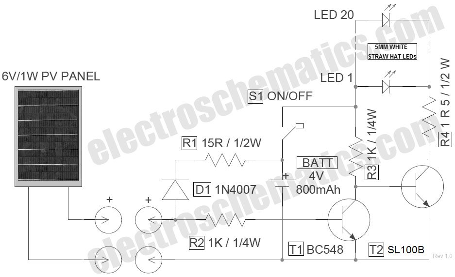
The circuit for the LED solar lantern lights is designed using a 6V/1W solar panel (photovoltaic panel) and a 4V/800mAh lead-acid battery. The schematic for the LED solar lantern circuit incorporates a solar panel that converts sunlight into electrical energy....
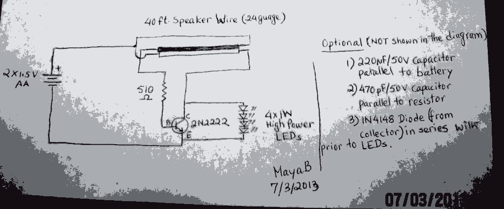
The post discusses a Joule Thief circuit that drives and illuminates four 1-watt LEDs using a single 1.5V pencil cell. The Joule Thief circuit is a minimalist boost converter designed to extract energy from low-voltage power sources, such as a...