
Light-Controlled Pond Pump

The circuit utilizes a straightforward design that integrates various electronic components to achieve its intended functionality. The power supply section begins with a 25VAC transformer, which is converted to DC using a bridge rectifier. The rectified voltage is smoothed by a large capacitor, ensuring a stable power supply for the rest of the circuit. The 7812 voltage regulator is crucial for providing a consistent +12V output, which is necessary for the reliable operation of the electronic components.
The light sensing mechanism relies on the LDR1 photocell, whose resistance varies with light intensity. This variation is effectively translated into a control signal for the transistors. The use of a trimpot allows for fine-tuning of the light sensitivity, enabling users to set the exact threshold at which the pump should activate. This feature is particularly useful in varying environmental conditions and ensures that the pump operates only under the desired circumstances.
Transistors Q1 and Q2 are configured to create a switching mechanism. When Q1 is activated by low light conditions, it allows current to flow to Q2, which subsequently energizes the relay. This relay acts as a switch for the pump, providing the necessary current to operate it. The inclusion of a capacitor across the LDR prevents rapid fluctuations in light from causing erratic pump behavior, thereby enhancing stability.
The manual control switch (S1) offers flexibility, allowing users to override the automatic system if needed. This is particularly useful for maintenance or when specific conditions require manual intervention. The entire assembly is compact and housed securely, ensuring durability and ease of installation in outdoor environments.
In conclusion, this circuit exemplifies a practical application of basic electronic principles to solve a common problem in garden maintenance, providing convenience and efficiency while ensuring the health of the pond ecosystem.This circuit was constructed to control the pump in a garden pond, so that it automatically turns on at dawn and off again at dusk. Not only does this mean that we don`t have to get cold and wet when turning the pump on or off manually but it`s also one less job for our kind neighbours when we go away on holidays!
The controller is powered from th e pump`s existing 25VAC mains transformer. A bridge rectifier (BR1) and 1000 F capacitor provide DC power to the circuit. For dependable operation, this is regulated to +12V by a 7812 regulator (REG1), while a red LED (LED1) provides power-on indication. The light sensor (LDR1) is a Cadmium-Sulphide photocell obtained from Tandy Electronics. The photocell forms a voltage divider with trimpot VR1. With no light on the photocell, the voltage on the base of Q1 is greater than 0. 6V and therefore it is switched on. When light falls on the photocell, its resistance decreases, lowering the bias voltage on Q1 and switching it off.
This in turn allows Q2 to switch on, energised the relay and turning on the pond pump. In use, the 2. 2M © trimpot is adjusted so that the pump cuts out at the desired light level. A 47 F capacitor across LDR1 prevents transient light changes from affecting circuit operation. S1 is a miniature SPDT centre-off toggle switch, allowing the pump to be turned on or off manually, or switched to automatic mode. The circuit was constructed on a small protoboard from Dick Smith Electronics (Cat. H 5604) and housed in a bulkhead box, which was then attached to the transformer housing. The photocell was soldered to a length of figure-8 cable and sheathed in a short length of heatshrink tubing to form a light probe.
This was attached to a nearby fence post to provide suitable exposure to sunlight. 🔗 External reference
Related Circuits
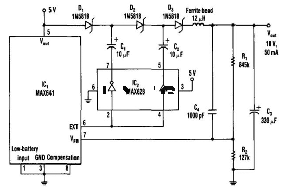
The DC-DC converter replaces a voltage tripler for the external inductor and diode typically associated with the switching regulator, IC1. Inverting and non-inverting amplifiers in the MOSFET driver (IC2) activate a diode-capacitor tripling network (D1 through D3, C1 through...
This device emits intermittent beeping for approximately two seconds when a whistle is detected from a person within a range of around 10 meters. The first two inverters in IC1 function as audio amplifiers. IC1A amplifies the signal captured...

MP3 players have gained immense popularity, especially the compact memory-stick format, which allows for easy portability and personal music enjoyment on the go. However, when sharing music with others, these players often lack sufficient power. A solution to this...

A simple Sump Pump Control Circuit using NE555. The described circuit utilizes the NE555 timer integrated circuit (IC) to create a control system for a sump pump. The NE555 can be configured in various modes, but for this application, it...
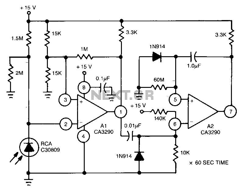
This circuit utilizes the CA3290 BiMOS dual voltage comparator to detect variations in the current of a light-emitting diode (LED). The output from the comparator triggers A2, a one-shot timer. If the light source to the photodiode is disrupted,...
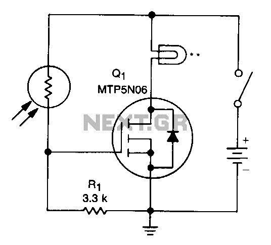
A school drama required lamps that automatically turned on and off in sync with the spotlights. The lamp switching system needed to be wireless, durable, reliable, simple, and cost-effective. With the stage and spotlights turned off, minimal light reaches...