
40KHZ LED TEST SIGNAL GENERATOR
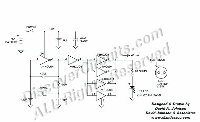
The circuit operates at a frequency of 40 kHz, determined by the crystal oscillator, which provides stable frequency output essential for applications requiring precise timing. The oscillator generates square wave signals that are used to modulate the infrared LED. The LED is driven by pulses of 40 mA, ensuring sufficient intensity for effective infrared transmission.
The crystal oscillator typically consists of a quartz crystal, which is connected in a feedback loop with an amplifier to maintain oscillation. The output of the oscillator can be connected directly to the infrared LED, often through a transistor or a driver circuit to handle the higher current requirements. This configuration allows for efficient switching of the LED, producing strong infrared pulses suitable for remote control applications or optical communication.
To ensure optimal performance, appropriate resistors and capacitors are used to stabilize the oscillator circuit and filter any noise. Additionally, the design may incorporate protective diodes to prevent back EMF from affecting the oscillator during operation. The circuit can be powered using a suitable DC supply, ensuring that the voltage levels are compatible with the components used. Overall, this setup provides a reliable and effective means of generating infrared signals for various electronic applications.This 40KHz crystal controlled oscillator circuit drives an infrared LED with powerful 40ma pulses 🔗 External reference
Related Circuits
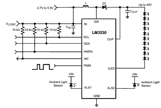
A simple white LED driver circuit can be designed using the LM3530 high-efficiency white LED driver IC, which features programmable ambient light sensing capability and an I2C compatible interface. The LM3530 LED driver can control up to 11 series...
This circuit generates a stable 1 kHz sine wave using the inverted Wien bridge configuration (C1-R3 & C2-R4). It features a variable output, low distortion, and low output impedance to ensure good overload capability. A small filament lamp provides...
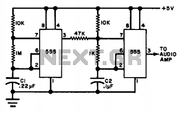
The circuit utilizes either two 555 timers or a single dual timer. Capacitor C1 regulates the speed of the warble effect, while capacitor C2 defines the pitch. The specified values are expected to generate a notably distinctive signal. The described...
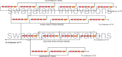
The following article outlines a sophisticated LED sequencing and diverging ring light that can serve as a tail brake light in vehicles. This circuit concept was proposed by a dedicated reader, Mr. Bobby. The design aims to create a...
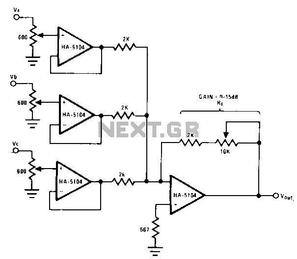
This circuit employs buffer stages to mitigate channel crosstalk through the mixer resistor network. The potentiometers utilized in each stage facilitate convenient signal strength adjustments while ensuring input impedance matching at the 600-0 audio standard. Additionally, the feedback resistor...
The timing must be exact to get those high voltage spikes. I used a tiny magnet on the rotor, that triggered a reed switch allowing the relay to pulse the energy from the recovery coil to the primary battery....