
40m TRANSMITTER

The 40-meter transmitter described utilizes two vacuum tubes, specifically the 6AU6 and 6GV8, to generate radio frequency signals for amateur radio communication. The 6AU6 is a pentode tube often used in RF amplification, while the 6GV8 is a dual triode that can be employed for oscillator and amplifier functions within the circuit.
The design of this transmitter is relatively straightforward, making it accessible for hobbyists and engineers with basic knowledge of electronics. However, caution is advised due to the presence of high voltages, which are typical in tube-based circuits. Proper insulation, safety equipment, and adherence to standard electrical safety practices are essential during construction and operation.
The transmitter's performance can be optimized by experimenting with a Variable Crystal Oscillator (VXO) coil, which allows for fine-tuning of the operating frequency. This adjustment is crucial for achieving the desired frequency shift and maintaining stability in transmission. For those seeking additional insights and guidance, consulting older editions of the ARRL Handbooks is recommended, as they provide valuable information on the principles of valve transmitters and practical construction techniques.
In terms of circuit design, the transmitter will typically include a power supply section to provide the necessary high voltage for the tubes, along with signal coupling components, such as capacitors and resistors, to ensure proper operation. An output stage will be necessary to match the transmitter to an antenna, facilitating effective transmission of the radio signals generated by the tube oscillators.This is a 40 meter transmitter which uses two valves, the 6AU6 and 6GV8. The construction is easy. Just be carefull due to high voltage present. Experiment with VXO coil for best frequency shift. See old ARRL Handbooks for further information on building simple Valve transmitters. 🔗 External reference
Related Circuits
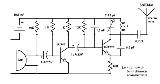
This simple-to-assemble FM transmitter can effectively transmit voice signals over an impressive range. By adjusting the trimmer, the signal can be heard on a nearby radio. The transmitter operates within a frequency range of 88-108 MHz and has a...
Here is the schematic, PC board pattern, and parts placement for a low powered FM transmitter. The range of the transmitter when running at 9V is about 300 feet. Running it from 12V increases the range to about 400...
The standard circuit will display directly in Hz (1MHz max), and there is a separate on board divider that will allow you to display directly in KHz (approx 40MHz max). Because the display reads directly in Hz or KHz...
Maxim has introduced a series of five integrated oscillator building blocks in the MAX260x series, covering a frequency range of 45 to 650 MHz. The MAX2606 is designed for the VHF band, allowing frequency variation of approximately ±3 MHz...
This schematic represents an FM transmitter capable of delivering an output power between 3 to 3.5 W, operating within the frequency range of 90 to 110 MHz. While the stability of the circuit is acceptable, the integration of a...
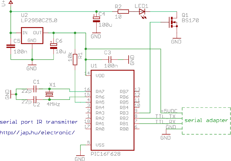
This is a programmable infrared (remote control) transmitter, which can be controlled from a PC serial port. It is capable of sending many remote control formats, including the Philips RC-5 standard. Exact formats with the timing parameter names are...