
40W audio amplifier
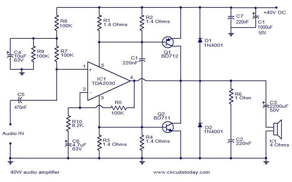
The described 40W power amplifier circuit leverages the TDA2030, a robust audio amplifier IC known for its ability to deliver high output power with minimal distortion. The circuit design is streamlined, utilizing a limited number of components, which enhances reliability and ease of assembly. The absence of a dual power supply simplifies the design, making it suitable for various applications where space and cost are considerations.
The input signal is coupled to the TDA2030's non-inverting input via a DC decoupling capacitor (C5), which blocks any DC offset present in the input signal, allowing only the AC component to pass through. This ensures that the amplifier operates effectively without biasing issues. The TDA2030 amplifies the voltage of the incoming signal, and as it does so, the current drawn from the power supply varies dynamically based on the amplitude of the input signal.
The output from the TDA2030 is directly related to the power supply current fluctuations, which are critical for the operation of the complementary transistors Q1 and Q2. These transistors are configured to provide additional current amplification. Q1 is responsible for amplifying the positive supply variations, while Q2 amplifies the negative supply variations. This complementary configuration allows for efficient handling of the output signal, resulting in improved performance and fidelity.
Overall, this circuit effectively combines the strengths of the TDA2030 with the current amplification capabilities of the complementary transistor pair, resulting in a powerful audio amplifier suitable for various audio applications. The design's simplicity, combined with its effective amplification capabilities, makes it an excellent choice for both hobbyists and professionals in the field of audio electronics.This is a very excellent 40W power amplifier design using TDA2030 IC and two transistors. The circuit employs only few components and does not require a dual power supply. The input signal is coupled to the non inverting input of TDA2030 through the DC decoupling capacitor C5. The TDA 2030 performs the major part of voltage amplification. As the I C performs amplification, the power supply current to the IC varies according to the input signal. The variations in the positive supply pin are coupled to the base of Q1 and variations in the negative supply pin are coupled to the base of Q2. The major part of current amplification is done by these two complementary transistors. 🔗 External reference
Related Circuits
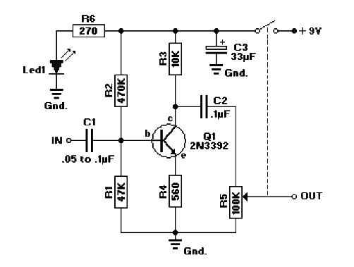
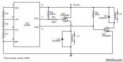
The circuit diagram represents a booster for an audio application. It features a linear potentiometer R5 with a resistance of 100K ohms, which includes an on/off switch. The capacitor C1 should be selected with a value between 0.05 µF...
Fans are eager to create a high-quality amplifier; however, many of the most notable publications on the circuit tend to be overly complex and difficult to implement. This article describes a pure Class AB output stage amplifier circuit that...
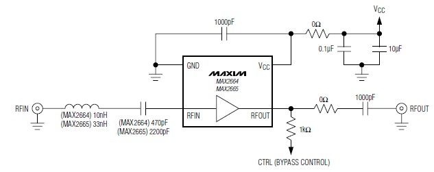
These devices feature a broadband low-noise amplifier (LNA) with an integrated bypass switch. The MAX2664 operates within the UHF frequency range of 470 MHz to 860 MHz, while the MAX2665 functions within the VHF frequency range of 75 MHz...
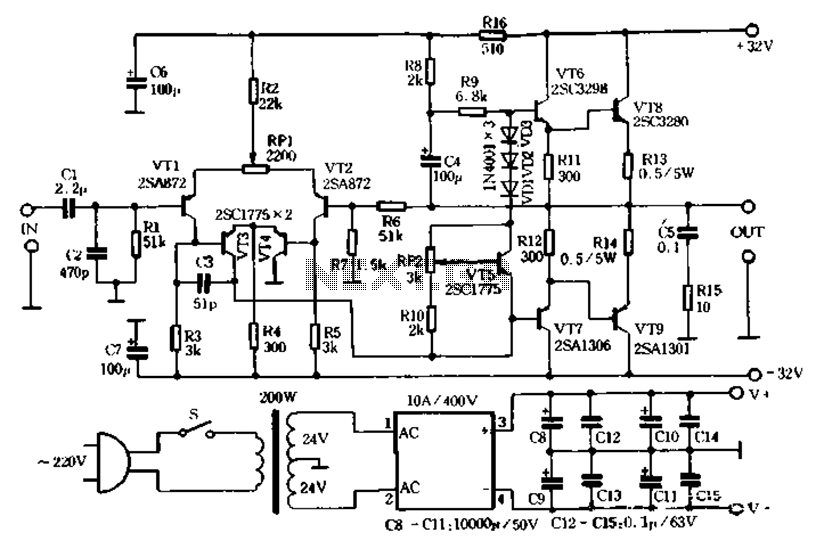
This device is a 2 x 2, 500W RMS stereo amplifier that is super-light and features a switching-mode power supply. The design only displays one channel, but the power supply supports both channels. The amplifier should be duplicated, but...
Circuit stereo TDA2822 audio power amplifier circuit schematics. In this series, the TDA2822M IC is utilized as the primary amplifier. Additionally, alternatives such as KA2209 and NJM2073 can also be employed. The TDA2822 audio power amplifier circuit is designed to...
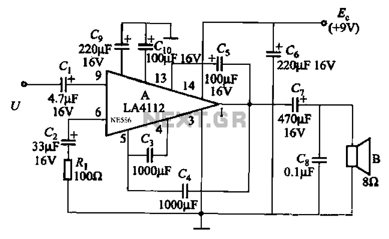
Audio power amplifier circuit utilizing the LA4112 integrated power amplifier along with additional components as shown in the figure. The audio power amplifier circuit based on the LA4112 integrated power amplifier is designed to deliver high-quality audio amplification for various...
Warning: include(partials/cookie-banner.php): Failed to open stream: Permission denied in /var/www/html/nextgr/view-circuit.php on line 713
Warning: include(): Failed opening 'partials/cookie-banner.php' for inclusion (include_path='.:/usr/share/php') in /var/www/html/nextgr/view-circuit.php on line 713