
5 W ATV TRANSCEIVER
The transmitter operates within the 440 MHz band and is designed for amateur television (ATV) applications. The integration of both video and audio sections allows for simultaneous transmission, making it suitable for broadcasting purposes. The output power of five to six watts PEP is adequate for effective transmission over moderate distances, ensuring a clear signal for receiving stations.
The use of PIN diodes for channel switching provides rapid and reliable transitions between the three available channels, enhancing the versatility of the transmitter. These diodes are known for their low insertion loss and high switching speed, which is critical in maintaining signal integrity during channel changes.
The downconverter section of the schematic typically involves the mixing of a local oscillator signal with the incoming RF signal, allowing for the downconversion of the frequency to a more manageable level for further processing. This section is crucial for ensuring that the transmitted signals remain within the required frequency specifications while also facilitating the reception of incoming signals.
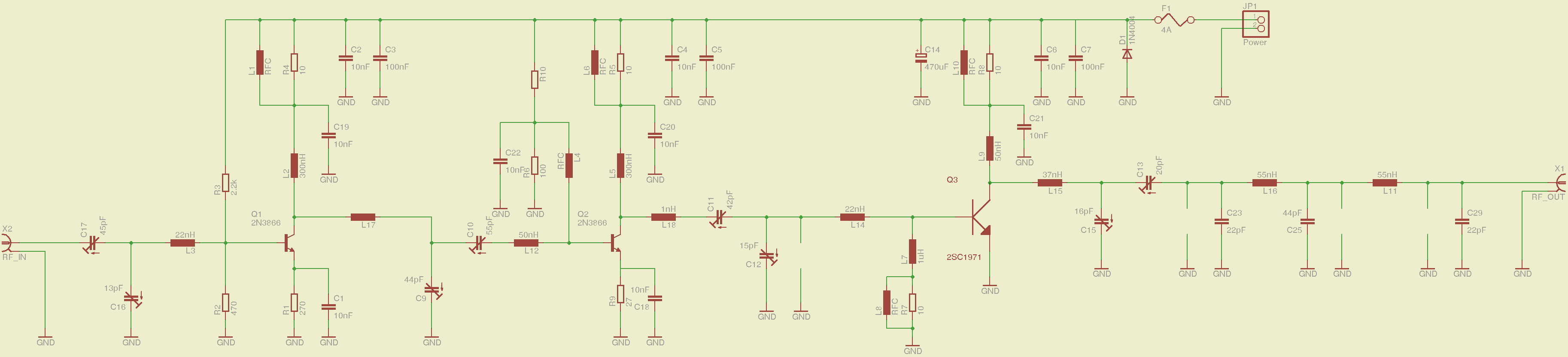
Overall, the described transmitter schematic is a robust design that effectively combines video and audio transmission capabilities, making it a valuable component for ATV enthusiasts and professionals in the field. The thoughtful integration of components and the strategic use of technology such as PIN diodes contribute to the efficiency and performance of the device.For the transmitter schematic (part of this transceiver), see entry entitled S-W ATV Transmit-ter for 440 MHz, Fig. 5-1. The downconverter portion is shown here.This transmitter contains both a video and sound section. Five to six watts PEP on synch tips of NTSC video are produced. Three channels are available. Channel switching is via PIN diodes. Power.. 🔗 External reference
Related Circuits
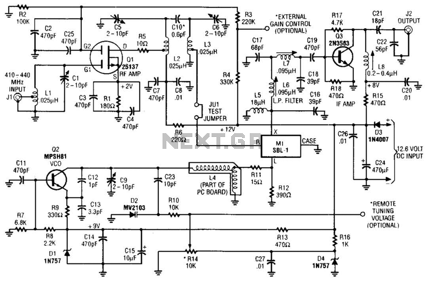
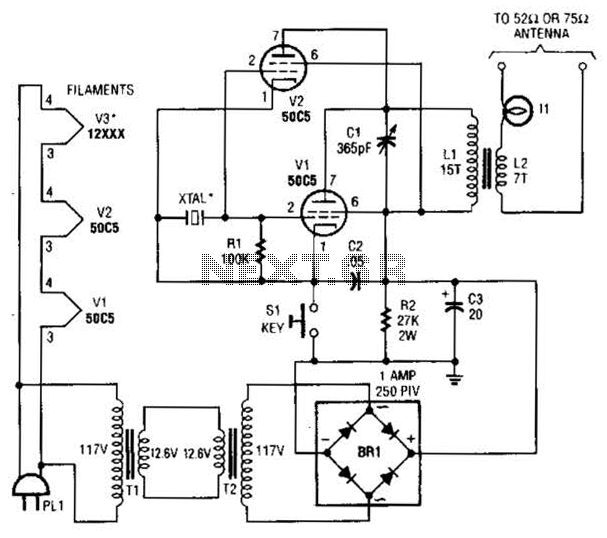
This RF converter converts amateur TV signals in the 420 to 450 MHz region to VHF channel 3 or 4, allowing reception of those signals on a standard TV receiver. RF amplifier Q1 feeds mixer M1, and Q3 acts...
In general, the transceiver switches the 4-element 1500 ohm xtal BPF ends between the inputs and outputs of the two SA602s to reverse the signal flow for R/T operation. Since no IF amplifier is used in the design, 20...
This article provides a detailed overview of a 70 cm wideband transceiver designed for duplex operation. The modules operate within a 200 kHz wide duplex channel, selectable from 430-440 MHz with a 100 kHz channel spacing. Initial prototypes were...

The 7MHz CW transceiver is constructed using the MC3362P integrated circuit, originally intended for a 10MHz band transceiver. Due to concerns regarding unexpected neighboring spurious signals, the frequency was altered to 7MHz, leading to the completion of the transceiver....
A 2-meter ham radio transceiver that incorporates all necessary circuitry, specifically including a voltage-controlled oscillator (VCO) and phase-locked loop (PLL) for frequency synthesis, a low noise amplifier (LNA) for the receiver front-end, a power amplifier (PA) for the radio...
This low-power video transmitter is designed for remote control (R/C) applications, surveillance, or amateur radio purposes. It utilizes seven transistors within a crystal oscillator-multiplier RF power amplifier chain, along with a high-level video modulator. A supply voltage of 9...