
7MHz CW transceiver made with Motrola MC3362P

The 7MHz CW transceiver based on the MC3362P is a compact and efficient design tailored for amateur radio enthusiasts. The MC3362P integrated circuit serves as the core component, integrating essential functionalities such as double balanced mixers and local oscillators, which are pivotal for effective signal processing in both receiving and transmitting modes. The choice of 7MHz as the operating frequency allows for clearer communication, particularly in the presence of spurious signals that can affect performance in higher frequency ranges.
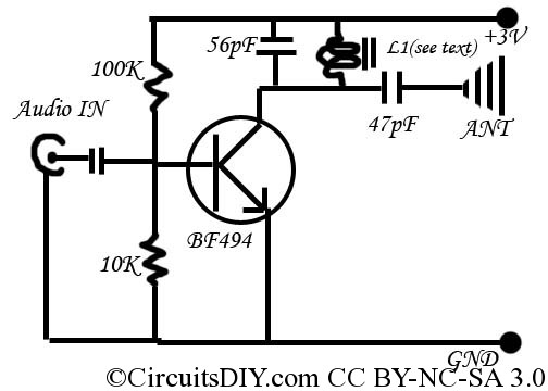
The circuit architecture employs a single super heterodyne configuration, which is advantageous for SSB and CW operations due to its ability to provide high selectivity and sensitivity. The use of the first mixer in the receiving circuit as the transmission mixer is a clever design choice that minimizes component count and saves space, contributing to the overall compactness of the device.
The inclusion of only two transistors in the transmitting output stage simplifies the design while maintaining adequate power output for effective transmission. The NJM386 operational amplifier enhances the AGC functionality, ensuring that the receiver can adapt to varying signal strengths, which is crucial for maintaining audio clarity and preventing distortion.
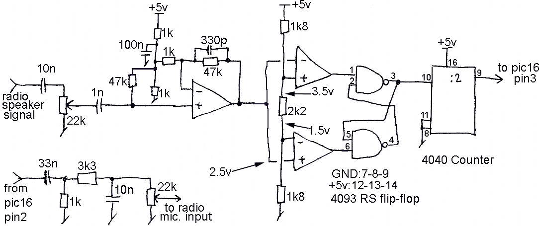
The transceiver's user interface, as depicted in the upper front panel photograph, is designed for ease of use. The arrangement of controls allows for intuitive operation, with the VFO knob enabling precise frequency adjustments. The RF and AF gain controls provide users with the ability to optimize signal levels for both transmission and reception.
The rear panel's DC power supply connector and M-type antenna connector are standard features in amateur radio equipment, facilitating easy integration with existing setups. The housing in the 'P-7' case not only protects the internal components but also provides a professional appearance, making it suitable for both personal use and public demonstrations.
As the MC3362P is no longer in production, users may need to consider the MC13135 as a viable alternative for future repairs or modifications. Overall, this transceiver represents a significant achievement in compact radio design, combining functionality with user-friendly features for effective amateur radio communication.The 7MHz CW transceiver made with MC3362P. I made a 7MHz CW transceiver by using the IC for the narrow band FM double super receiving circuit, MC3362P. I intended to make a transceiver for 10MHz band in the beginning. But, I was worried by the neighboring spurious signal which wasn`t expected, and I changed the plan. I changed frequency to 7MHz ba nd, and continued the production, and completed this transceiver. The CW transceiver made by MC3362P was introduced to the QST journal of December, `90 and January, `91 as well. (The article of the translation of selected passages appeared in August, 91 issue of the JA-CQ journal as well.
) Because 2 set of double balanced mixers and local oscilators are built in this IC, it is suitable for the single super heterodyne receiver of SSB/CW. I made the whole circuit scale compact by using the 1st mixer of the receiving circuit as the mixer for the transmission as well.
I am only using 2 transistors of the transmitting output stage, 1 FET of the reception AGC, NJM386(second source of LM386) and 4 transistors such as the transmitting-receiving switch, except for MC3362P. But, though it is very much disappointed, it seems to finish the production of MC3362P by the end in 1998.
(The Motrola company recommends MC13135 as the substitut. ) I included this transceiver into the case of `P-7` which was kit of the Mizuho company. As for being reflected by the photograph of the upper front panel, a slide switch under that is a power switch with a stereophonic headphones jack, a key jack, a VFO knob, RF gain, AF gain from the left. It is the power supply connector of DC6 - 9V and a M-type antenna connector that it is reflected by the photograph of the rear panel.
🔗 External reference
Related Circuits
The reason for this project was to facilitate a quick installation for a local friend 10 km away, enabling the start of real-life testing to identify and resolve bugs and problems before releasing it to other users. The software...

Intercom walkie-talkies represent an advanced application of crystal oscillators for voice transmission. Utilizing a crystal-locked oscillator for voice transmission is complex due to the oscillator's fixed frequency, which is challenging to modulate. The primary method for achieving this involves...
This is a simple and inexpensive FM transmitter. The circuit operates at a low voltage using a CR2025 3V battery with low current consumption. The total size of this FM transmitter, including the battery but excluding the antenna, is...
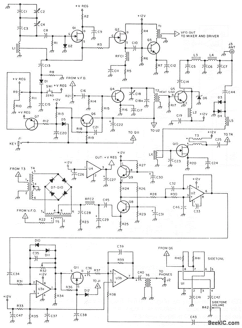
This is a 3-W, single-circuit board, VFO-controlled CW transceiver for 40 or 30 meters, featuring a direct-conversion receiver with audio filtering, Receiver Incremental Tuning (RIT), and speaker level audio volume. The transmit frequency is generated by Q1 and its...

This design circuit is for a simple 27MHz transmitter that produces a carrier signal. The circuit generates an unmodulated 27MHz signal, which can be received by a compatible receiver. The transmitter operates as a basic crystal oscillator, with the...

The relay power in the linear circuit is derived from a -120 V bias supply, while the transmit keying output from the Kenwood device is +12 V with a maximum current of 10 mA. A critical component of this...