
5 Watt UHF TV Linear amplifier
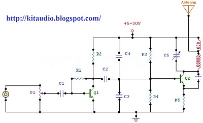
The circuit functions as a linear amplifier specifically designed for UHF TV transmission applications, operating effectively within the frequency range of 450 to 800 MHz. The amplifier achieves a gain of 7 dB, making it suitable for boosting weak signals typical in UHF broadcasting. The input signal level can be in the range of 1 to 1.5 Watts, which allows for compatibility with various UHF transmitters.
To ensure optimal performance, a double-layer printed circuit board (PCB) is recommended. The second layer of the PCB should be connected to ground to provide improved shielding and signal integrity, reducing potential interference and noise that could affect the amplifier's performance.
The circuit requires a stabilized power supply, rated at 25 volts and capable of supplying at least 5 Amps. This ensures that the amplifier operates reliably under various load conditions without voltage fluctuations that could compromise its performance.
The active component used in this design is a transistor housed in a SOT-122A package. It is critical to handle this component with care, as it is noted to be toxic. Proper safety measures should be taken when working with the circuit to mitigate any health risks associated with the transistor.
Tuning the amplifier can be accomplished by adjusting the two variable capacitors incorporated into the design. This allows for fine-tuning of the circuit to achieve the desired frequency response and optimize signal amplification.
Additionally, it is essential to use heat sinks for both transistors, particularly for the BLW89 transistor. This is necessary to dissipate heat generated during operation, preventing thermal overload and ensuring the longevity and reliability of the amplifier circuit. Proper thermal management is crucial in maintaining the performance and stability of the amplifier under continuous operation.This small circuit is a Linear amplifier for driving small UHF TV transmitters. Its gain is 7dB and can amplify a signal between 450-800 MHz. You can drive the circuit with 1 to 1,5 Watts signal. Better use double layer PCB with the second layer connected to earth. Use a stabilized power supply 25 volts and at least 5Amps. The transistor case is the SOT-122A and be careful because the transistor is very toxic for your health. Tuning can be achieved turning the two variable capacitors. Do not forget to use heat sink for both transistors, specially for the BLW89 and it would 🔗 External reference
Related Circuits
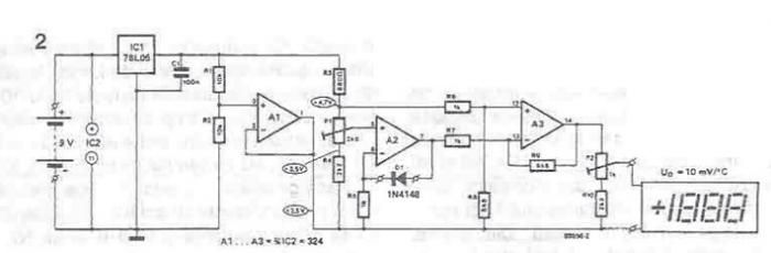
A simple thermometer can be constructed using operational amplifiers and a standard or protective diode, such as the 1N4148, as depicted in the electronic diagram below. A constant reference voltage is supplied to the non-inverting input of the operational...
The circuit is a microphone amplifier designed for low impedance microphones, approximately 200 ohms. It operates with stabilized voltages ranging from 6 to 30 VDC. If the impedance adapter section with T1 is not constructed, the circuit can be...
Construct a basic audio amplifier utilizing transistors. While integrated circuit (IC) designs are available for this purpose, the intention is to use transistors to gain practical knowledge about their amplification capabilities. The article "Amplifier Basics - How Amps Work...

The circuit utilizes six 12-volt lead-acid batteries to power the load. Three batteries are connected in series to generate 36 volts, while the other three are connected in parallel to maintain 12 volts. The total discharge current is 30...
These devices are low-cost, high-speed, dual JFET input operational amplifiers featuring an internally trimmed input offset voltage (utilizing BI-FET II technology). They require low supply current while maintaining a large gain-bandwidth product and fast slew rate. Additionally, well-matched high-voltage...
The circuit is a radio frequency (RF) oscillator functioning at approximately 100 MHz. Audio signals captured and amplified by an electret microphone are routed to an audio amplifier stage constructed around the first transistor. The output from the collector...
Warning: include(partials/cookie-banner.php): Failed to open stream: Permission denied in /var/www/html/nextgr/view-circuit.php on line 713
Warning: include(): Failed opening 'partials/cookie-banner.php' for inclusion (include_path='.:/usr/share/php') in /var/www/html/nextgr/view-circuit.php on line 713