
Mark Harrington Audio Tracer
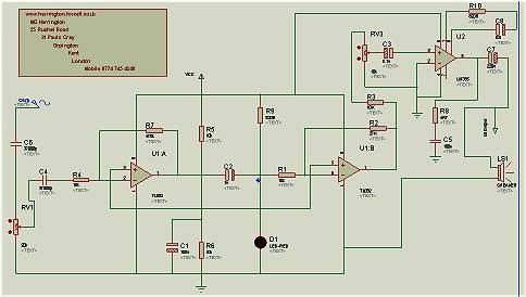
The Mark Harrington Audio Tracer is a specialized audio processing circuit designed to enhance and analyze audio signals. At its core, the circuit utilizes an operational amplifier (op-amp) as the primary signal processing element. The audio input is initially coupled to the non-inverting input of the first stage op-amp through a series of components including capacitor C6, variable resistor RV1, capacitor C4, and resistor R4.
Capacitor C6 serves to block any DC offset from the incoming audio signal, allowing only the AC audio components to pass through to the op-amp. The variable resistor RV1 is used to adjust the gain of the op-amp stage, providing flexibility in the amplification of the audio signal based on the specific requirements of the application. This feature is critical for tailoring the output level to match downstream processing equipment or for adjusting the overall loudness of the audio output.
Capacitor C4 is employed to filter high-frequency noise that may be present in the audio signal, ensuring that only the desired frequency range is amplified. Resistor R4 plays a vital role in setting the gain of the op-amp and stabilizing the circuit by providing feedback, which is essential for maintaining linearity in the amplification process.
Overall, this circuit configuration allows for effective audio signal processing, making the Mark Harrington Audio Tracer a valuable tool for audio engineers and enthusiasts looking to analyze and manipulate audio signals with precision. The combination of capacitors, resistors, and the op-amp enables a versatile platform for various audio applications, from basic amplification to more complex signal analysis tasks.Mark Harrington Audio Tracer. The audio input is fed into the first stage op amp via C6 , RV1 , C4, R4.. 🔗 External reference
Related Circuits
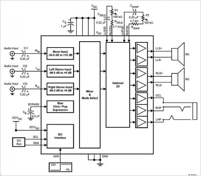
The LMC568 is an amplitude-linear phase-locked loop that includes a linear voltage-controlled oscillator (VCO), fully balanced phase detectors, and a carrier detect output. It utilizes LMCMOS technology to achieve high performance while maintaining low power consumption. The VCO features...
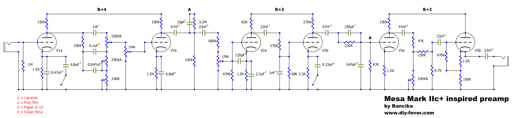
The Mark IIc+ amplifier is highly regarded and sought after, with only 1500 units produced in the 1980s, now valued between $4000 and $5000. One notable artist associated with this amplifier is John Petrucci. Due to affordability issues, a...
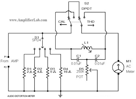
A circuit diagram of an audio distortion meter is presented here. An audio distortion meter is utilized to measure Total Harmonic Distortion (THD). The audio distortion meter is an essential tool in audio engineering, designed to quantify the level of...
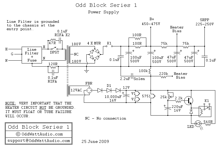
A schematic of the ability accumulation is presented below. Similar to the amplifier schematic, the ability accumulation design is © OddWatt Audio, and permission to host the schematic on this platform has been granted by OddWatt Audio. The schematic...
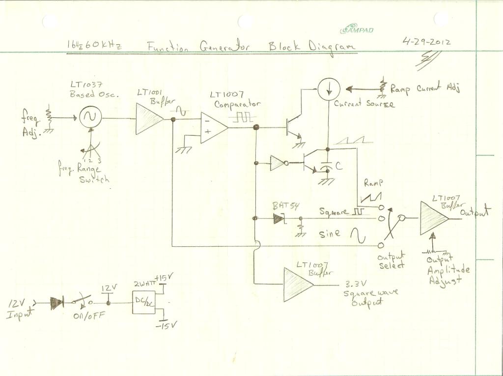
Most blog posts involve short 3-4 hour projects or hacks that are built for learning and enjoyment. It was time to develop something more substantial. The project described appears to focus on creating electronic circuits that can be completed within...
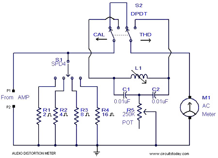
This is a simple 1 kHz audio distortion meter designed to measure the Total Harmonic Distortion (THD) on any load at any output power. The circuit allows for the selection of load impedances of 2, 4, 8, or 16...