
555 automatic power-protection circuit diagram
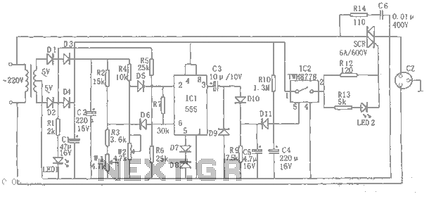
The automatic power protection circuit is designed to safeguard electronic devices from voltage fluctuations that could potentially cause damage. The step-down rectifier circuit serves as the initial stage, converting the input AC voltage to a lower DC voltage suitable for the subsequent components. This step-down operation is crucial in ensuring that the voltage levels remain within safe operating limits.
The overvoltage and undervoltage detection circuits are integrated to monitor the output voltage continuously. They employ voltage sensing mechanisms to detect any deviations from the predefined voltage thresholds. When an overvoltage condition is detected, the circuit activates protective measures, such as disconnecting the load or triggering an alarm, to prevent damage to the connected devices. Conversely, in the event of undervoltage, the circuit can initiate a shutdown procedure to safeguard the equipment from insufficient voltage levels that could lead to malfunction or damage.
The delay switch control circuit plays a vital role in managing the timing of the power restoration after a fault condition has been detected. This delay is essential to allow transient conditions to stabilize before reapplying power to the load. It prevents unnecessary cycling of the power, which could lead to further issues.
Overall, this automatic power protection circuit is an essential component in modern electronic systems, providing robust protection against voltage anomalies and ensuring the reliability and longevity of sensitive electronic devices.Shown automatic power-protection circuit. This protection consists of step-down rectifier circuit, overvoltage and undervoltage detection circuit, delay switch control circuit. Wherein the step-down circuit for the entire rectifier circuit DC voltage.
Related Circuits
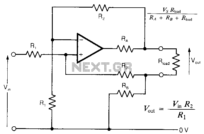
In intrinsically safe applications, it is sometimes necessary to separate sections of circuitry using resistors that limit current under fault conditions. The circuit presented offers an accurate analog output with effectively zero output impedance, despite the presence of resistors...
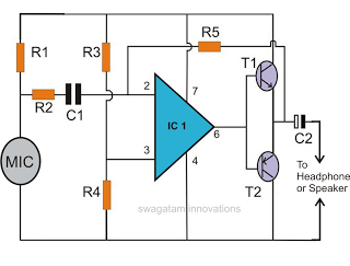
This document discusses the creation of an electronic spy bug circuit using two methods: one involving a wired connection from the transmitter to the receiver, and the other being a completely wireless setup capable of eavesdropping on conversations up...

The circuit for the Digital Tachometer/RPM Counter consists of a few components. They should be connected according to the provided circuit diagram. The PIC used is on a demonstration board, meaning the clock, power, and ground pins are already...
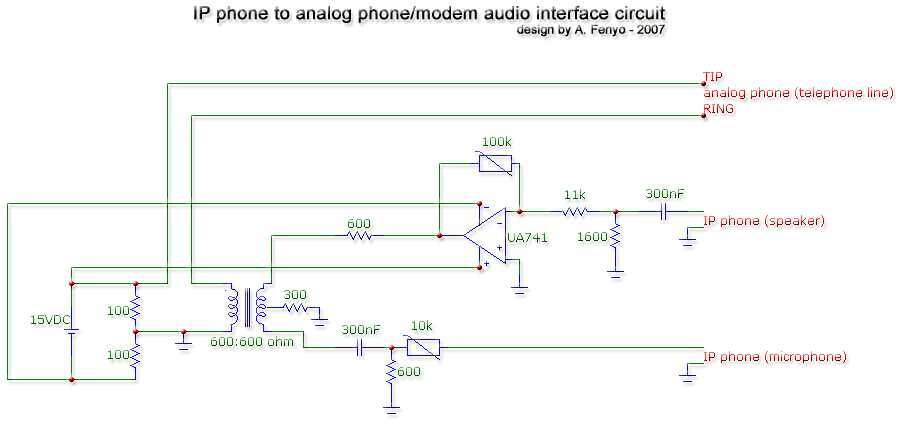
The transformer is a 600:600 ohm transformer, also referred to as a 1:1 ratio 600 ohm transformer. It has approximately the same number of turns on both the primary and secondary coils and is optimized for operation at a...
The circuit was designed to create a line preamplifier using double triode tubes. It consists of three parts, including the main preamplifier. The line preamplifier circuit utilizing double triode tubes is structured to enhance audio signals by amplifying low-level signals...
This is a light sensor circuit designed to detect light and activate a relay. The circuit is straightforward and requires only a few components. The operation of the circuit is simple: when the photoresistor detects light, it will turn...
Warning: include(partials/cookie-banner.php): Failed to open stream: Permission denied in /var/www/html/nextgr/view-circuit.php on line 713
Warning: include(): Failed opening 'partials/cookie-banner.php' for inclusion (include_path='.:/usr/share/php') in /var/www/html/nextgr/view-circuit.php on line 713