
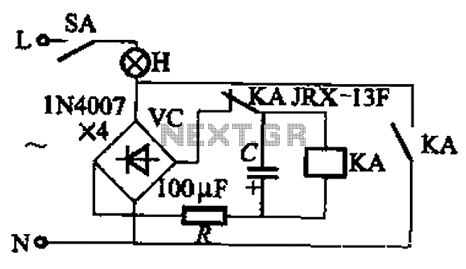
light sensor circuit
The light sensor circuit operates based on the principle of light detection through a photoresistor, also known as a light-dependent resistor (LDR). The photoresistor is a variable resistor whose resistance decreases with increasing incident light intensity. This change in resistance is crucial for triggering the transistor.
In the circuit, the photoresistor is connected in a voltage divider configuration with the 50K variable resistor. When light falls on the photoresistor, its resistance drops, causing the voltage at the base of the 2N2222 transistor to rise. The 2N2222 is a general-purpose NPN transistor that, when activated, allows current to flow from the collector to the emitter. This current flow is sufficient to energize the relay coil.
The relay serves as a switch that can control larger loads, such as lights or other electrical devices. A relay rated for 5-6 volts is recommended to ensure compatibility with the circuit's voltage levels. The relay contacts can be configured to either normally open (NO) or normally closed (NC) depending on the desired operation of the connected equipment.
The sensitivity of the light detection can be fine-tuned using the 50K variable resistor. By adjusting this resistor, the threshold at which the photoresistor will activate the transistor can be altered, allowing for greater flexibility in various lighting conditions.
It is essential to ensure that the circuit is powered by an appropriate voltage source that matches the relay's requirements, and that all components are rated for the expected load to prevent damage. Proper heat dissipation for the transistor may also be necessary, depending on the load connected to the relay. Overall, this light sensor circuit is a practical solution for automated lighting systems and other applications requiring light detection and control.This is a light sensor circuit which will detect light and switch on the relay. This light switch circuit is very simple and using only few components. Working of the circuit is simple, when the photoresistor receives light it will switch on the transistor 2N2222, when transistor become ON it will activate the relay switch and any equipment connec ted with the relay will become activated. Use 5-6 volt relay. The sensitivity of the circuit can be adjusted with 50K variable resistor. 🔗 External reference
Related Circuits
This is a highly sensitive envelope detector designed for AM radio applications. The circuit, illustrated in Figure 1, enables linear detection of weak signals with a modulation depth of 80-85%. The first stage (VT1) functions as a common-emitter amplifier...
This circuit assists in parking a car near a garage wall by providing distance alerts. LED D7 illuminates when the bumper-wall distance is approximately 20 cm. When the distance decreases to about 10 cm, both D7 and D6 illuminate,...
The EQ-2 is a 6-band graphic equalizer circuit. Each band is controlled by potentiometers RV1-6, which are designed as faders for improved visual indication of adjustments. However, standard potentiometers can also be used as replacements. At the center position...
This is basically a flasher circuit modified to turn on and off a bulb instead of a LED. It uses a 555 timer IC working as an astable multivibrator. The flashing rate can be varied from very fast to...
An average ability amplifier characterized by acceptable overall quality, while being simple in construction. It is frequently used in live loudspeakers. The design incorporates high-quality FET transistors, specifically HEXFET technology, which are voltage-controlled rather than conventional bipolar transistors. The...
The circuit illustrated in Figure 13-3 consists of two configurations: (a) a DC power supply and (b) an AC power supply. Both configurations are utilized to control a relay. The flash frequency of the relay is determined by the...
Warning: include(partials/cookie-banner.php): Failed to open stream: Permission denied in /var/www/html/nextgr/view-circuit.php on line 713
Warning: include(): Failed opening 'partials/cookie-banner.php' for inclusion (include_path='.:/usr/share/php') in /var/www/html/nextgr/view-circuit.php on line 713