
high voltage 555 audio modulated flyback
The described circuit utilizes a 555 timer in astable mode to generate a pulse-width modulated (PWM) signal that drives a MOSFET, which in turn powers a flyback transformer. The choice of MOSFET is critical; it must have a voltage rating significantly higher than the operational voltage to handle transient spikes and ensure reliability. The on-resistance of the MOSFET affects efficiency and heat generation, making it essential to select a component with low RDS(on).
The circuit configuration should include a suitable gate resistor to balance the speed of operation and protection against voltage spikes. The PWM frequency generated by the 555 timer must be tuned to match the resonant frequency of the flyback transformer for optimal performance, which can be achieved by adjusting the potentiometer values in the timing circuit.
The heat management strategy involves mounting the MOSFET on a heat sink with active cooling to dissipate heat effectively, especially under high duty cycle conditions. The design should also incorporate safety features such as flyback diodes to protect against voltage spikes and ensure stable operation.
In summary, the successful implementation of this circuit requires careful selection of components, precise tuning of frequencies, and effective thermal management to achieve a reliable audio-modulated flyback arc generator.I bricked my iPod shuffle, seems that the controller chip for the mini jack got wasted as it could no longer detect charger, PC connection or play music as it could not detect headphones. The arc have to be very short in order to limit the distortions of an unstable arc. The sound quality is low due to the way the audio modulation is implemented. There are basically 2 kinds of modern flybacks, television flybacks are driven near 15kHz and monitor flybacks are driven between 30-150Khz. Depending on which type we use, we have to adjust the frequency of the 555 timer to match the resonance of the flyback for maximum performance.
The voltage rating of the MOSFET (VDSS) needs to be 6 to 10 times higher than the supply voltage, reverse voltage spikes and EMF can be high enough to destroy the MOSFET if its too small. But we still need to use MOSFETs with a reasonable low on resistance (RDS(on). Try to find a MOSFET with a RDS(on) value not much higher than 0. 1 ohm, if you have problems try one with a lower RDS(on) value. Protect against surge voltages on the MOSFET gate, effectively this would require a much higher resistance, a high gate resistance would lower the operation speed significantly.
The values of a gate resistor could be anything between 10 ohm to 200 ohm, it all depends on the MOSFET, experimentation is needed. The alternative is complicated calculations involving data that is usually not available in standard data sheets.
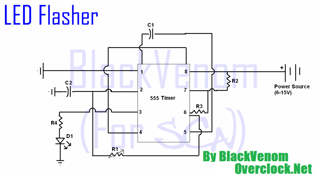
Pin 5 on the 555 timer is a direct access to the upper voltage comparator in the 555 timer. This allows us to pulse width modulate the output on pin 3 of the 555 timer. I wanted to do a audio modulated flyback arc with few components and a small form factor. I installed the MOSFET on a old CPU heat sink with fan, the 555 timer circuit is also installed underneath this heat sink, its then all put on the side of the flyback transformer with wire strips. The frequency output from the 555 timer is 26, 7 kHz at 59, 3% duty cycle. This is in the low end for a monitor flyback so further improvements will be adding a potentiometer to adjust frequency to match the resonant frequency of the flyback.
Its time to improve the driver with a variable frequency control so the driver can be used with most conventional monitor flyback transformers without changing any parts, but merely turn the potentiometer. I installed a 9K potentiometer as R1 and a 10K potentiometer as R2, I adjusted the potentiometers till I had a nice silent thin arc at about 15 mm length.
10K potentiometers can be used for both R1 and R2, I just used what I had at hand. Using a 555 calculator with the measured values of the potentiometers. R1 at 1K3 and R2 at 1K. Duty cycle is 69. 7% and frequency is 43700 Hz. Very reasonable for a monitor flyback. Compared to the old frequency I now have a longer and more silent arc. The arc is very very hot and I had to extend the copper wires where it is drawn between to avoid the heat being transferred far enough to start melting the flyback transformers casing. The 555 IC is not able to supply enough output current to drive a IRFP250N MOSFET at a high duty cycle, so the MOSFET will at times still be in linear mode and this causes excessive heating, which is why the heat sink is necessary.
Ok i suspect that my 555 is damaged or i should use a better substitute for the mosfet. . I have ordered a STB80NF10T4 N-Channel 100V 80A MOSFET and a IRF540 28A, 100V, 0. 077 Ohm, N-Channel Power MOSFET. and more 555`s i hope this will solve my problems im having. Also my power source is 6-14v 300ma ok i just found out that since my mosfet isnt rated a high enough amperage that i have to also tu 🔗 External reference
Related Circuits
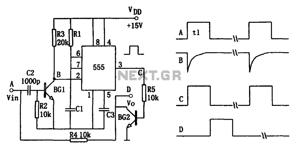
The pulse-width detection circuit is illustrated in the figure and consists of a differential circuit (R2, C2), an amplifier (BG1), a single stabilizing circuit (555, R1, C1), and various other components. The pulse signal Vin (depicted as waveform A)...
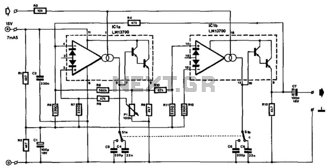
The frequency of this sine-wave oscillator is determined by a direct voltage, U, ranging from 0 to 15 V. The distortion in output signals of up to 10 Vpp does not exceed 1%. When the output is reduced using...
All of the components in this list are generally available through RadioShack for less than $20. It is highly recommended to use a breadboard for assembly, as mistakes are common for first-time builders, and soldering can complicate troubleshooting. This...
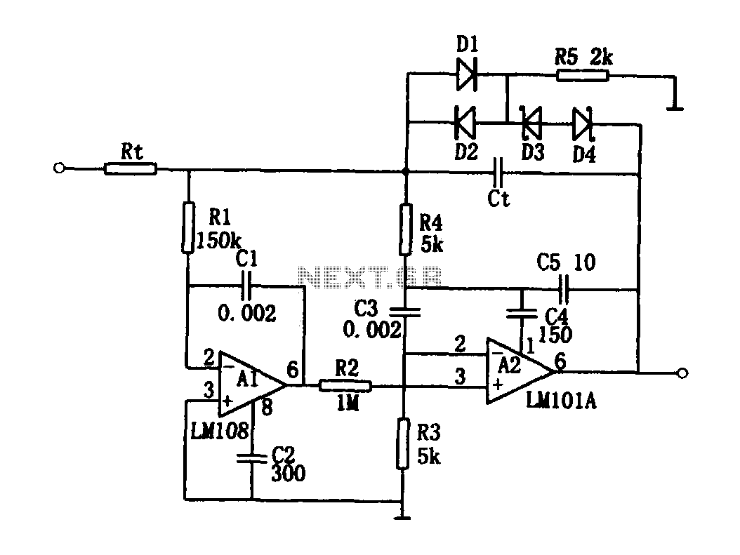
The high-speed integrating circuit is designed with an integration time constant circuit, RtCt, which offers a wide range. When the integrating capacitor Ct is not considered, A2 functions as a positive feedback compensation broadband AC amplifier. The negative feedback...
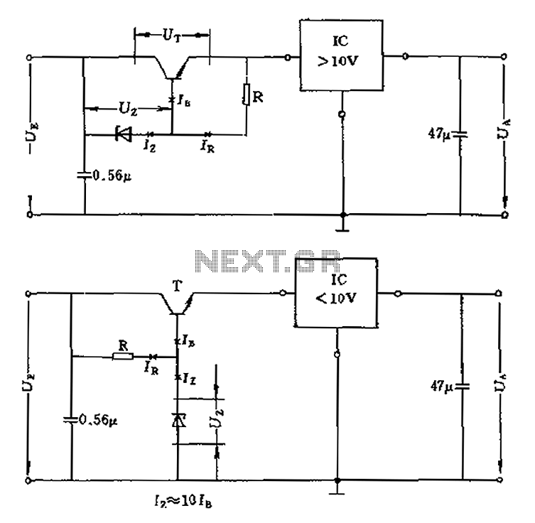
The voltage equation Ue = Ut + Ur + Ua indicates that the transistor voltage Ut will determine the maximum output voltage Ua. Additionally, Ur must be 2V. The voltage regulator's voltage value depends on the selection of Uz....
Switched-capacitor filters that are preset for a given bandwidth sometimes do not deliver the bandwidth or Q an application requires. By inverting the clock between two switched-capacitor bandpass filters, such as the MSFS1 from Mixed Signal Integration Corp, you...
Warning: include(partials/cookie-banner.php): Failed to open stream: Permission denied in /var/www/html/nextgr/view-circuit.php on line 713
Warning: include(): Failed opening 'partials/cookie-banner.php' for inclusion (include_path='.:/usr/share/php') in /var/www/html/nextgr/view-circuit.php on line 713