
555 capacitance tester circuit diagram
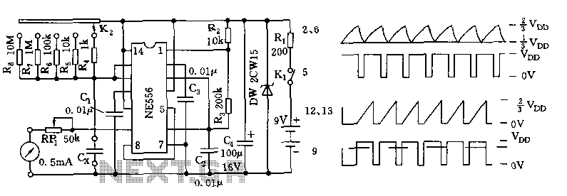
The described tester circuit utilizes the 556 timer, which contains two independent timing circuits that can be configured in various ways. The astable multivibrator configuration on the right side of the circuit generates a continuous square wave signal. The frequency of oscillation is determined by the resistors and capacitors connected to it, allowing for precise timing control. The use of R2 and R3 in the formula for frequency highlights the relationship between resistance and capacitance in determining the oscillation rate, which is critical for accurate capacitance measurement.
On the left side, the one-shot circuit is essential for generating a pulse in response to the square wave output. The duration of this pulse is governed by the selected range resistors R4 to R8 and the capacitance Cx being measured, providing flexibility in measurement capabilities. The inclusion of a potentiometer (RP1) for calibration ensures that the measurements can be fine-tuned against known capacitance standards, enhancing the accuracy of the tester.
The circuit is capable of measuring a wide range of capacitance values, which is particularly useful in electronics for testing capacitors in various applications. The clear division of measurement ranges enables users to select the appropriate setting for the capacitance being tested, ensuring that the circuit operates within optimal parameters. The output current range from 100µA to 0.5mA indicates the circuit's ability to handle different capacitance levels, making it a versatile tool for engineers and technicians working with electronic components.The tester consists of an dual time base circuit 556 and a number of RC components and other components. Illustrated by the right half of the circuit 556 (556 1/2) and R2, R3, C2, C3 and other components astable multivibrator, the oscillation frequency f = 1.44 / (R2 + 2R3) C2. Parameters correspond icon the frequency of about 60Hz or so. The left half of 556 (556 1/2) and C4, range resistors R4 ~ R8 and measured capacitance Cx constitute one-shot trigger circuit, 5 feet at the low level period of the square wave output of the right half, monostable flip, one-shot pulse width depends on the range resistors R4 ~ R8 and Cx, ie, t = 1.1 (R4 ~ R8) Cx.
According to the measured capacitance Cx select a different size range. Cx different capacities, the 556 9-pin output level correspondingly different, after potentiometer RP1 connected mA current file table or multimeter. RP1 potentiometer for the correction, for full-scale calibration with standard capacitance. 556 feet of each waveform diagram shown in Fig. B. This circuit can be measured capacitance of 10pF ~ 1uF within range. Range divided 10p ~ 100p ~ 1000p ~ 0.01u ~ 0.1u ~ 1u, corresponding to the current range of 100uA ~ 0.5mA.
Related Circuits

The circuit illustrated briefly flashes an LED to attract attention and remains illuminated as long as power is supplied. The circuit utilizes the well-known 555 timer integrated circuit (IC) configured as a standard astable multivibrator with resistors RA, RB,...

The TDA7262 integrated circuit, manufactured by ST Microelectronics, can be utilized to design a straightforward stereo audio amplifier project. This circuit can deliver a maximum output power of 20 watts per channel. The TDA7262 is a dual Hi-Fi audio...
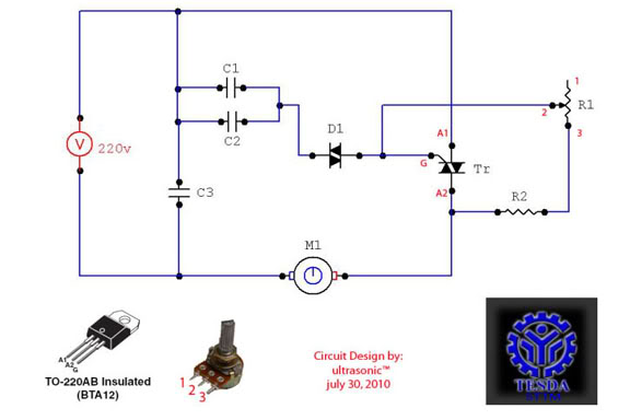
This circuit functions as a motor controller, allowing for easy control and variation of the RPM and phase of an AC motor. The power source is directly 220VAC, and it can handle a load of approximately 1 horsepower AC...
The circuit utilizes a dual sound multi-frequency encoding signal to modulate the emitted carrier frequency, forming a DTMF encoding wireless calling system. It incorporates the DTMF encoding circuit UM97085 and the decoding circuit YN9101 to create a micro wireless...
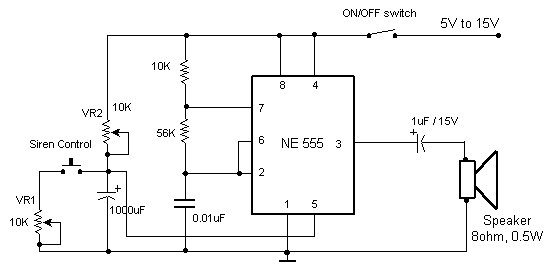
The circuit diagram of an electronic siren based on the NE555 timer produces a sound similar to that of a factory siren. The NE555 timer IC functions as an astable multivibrator with a center frequency of approximately 300 Hz....
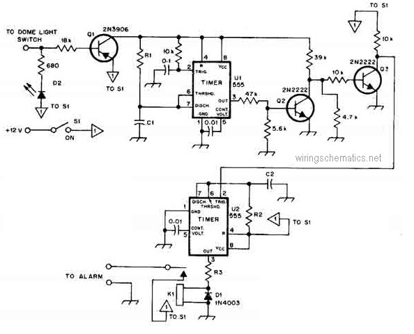
This circuit diagram represents a smart car alarm timer. This design is more advanced compared to traditional car alarm systems. When activated, the alarm remains active for 80 seconds, following an initial delay of 15 seconds. The smart car alarm...