
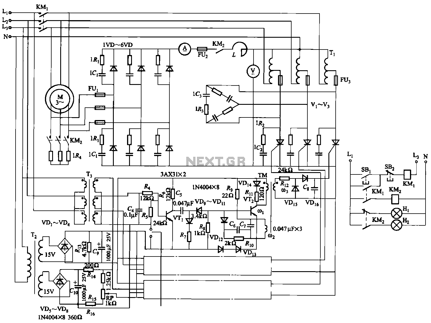
SPEED CONTROLLER CIRCUIT FOR AC MOTOR
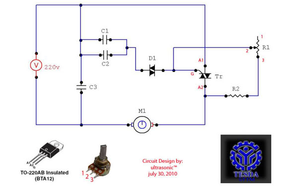
The motor controller circuit is designed to regulate the speed and phase of an AC motor, which is essential for applications requiring precise motor control. The circuit typically includes key components such as capacitors, resistors, and a triac or thyristor for phase control, enabling the adjustment of the motor's speed by altering the voltage and current characteristics.
A common configuration for such a motor controller might include a phase control circuit that utilizes a triac, which allows for the control of the AC waveform delivered to the motor. By adjusting the firing angle of the triac, the effective voltage and current supplied to the motor can be modified, thus controlling the speed. The circuit may also include a microcontroller or a potentiometer for user input, allowing for real-time adjustments to the desired RPM.
Safety features are critical in such designs. A fuse or circuit breaker may be included to protect against overload conditions, while proper heat dissipation measures, such as heat sinks for the triac, ensure reliable operation without overheating. Additionally, snubber circuits may be employed to protect the triac from voltage spikes caused by inductive loads.
The design should also consider the type of AC motor being controlled; for instance, single-phase motors may require different control strategies compared to three-phase motors. Proper filtering and decoupling capacitors can be included to minimize electrical noise and ensure stable operation of the control circuit.
In summary, this motor controller circuit offers a robust solution for varying the RPM and phase control of AC motors, making it suitable for a wide range of industrial and consumer applications.this circuit serves as a motor controller circuit to easily controlling or varying the RPM & Phase control of a AC motor. source: directly 220VAC Load: approx. 1hp AC motor (600w-1kw) CIRCUIT DIAGRAM: COMPONENT PARTLIST: C1 = 2G .. 🔗 External reference
Related Circuits
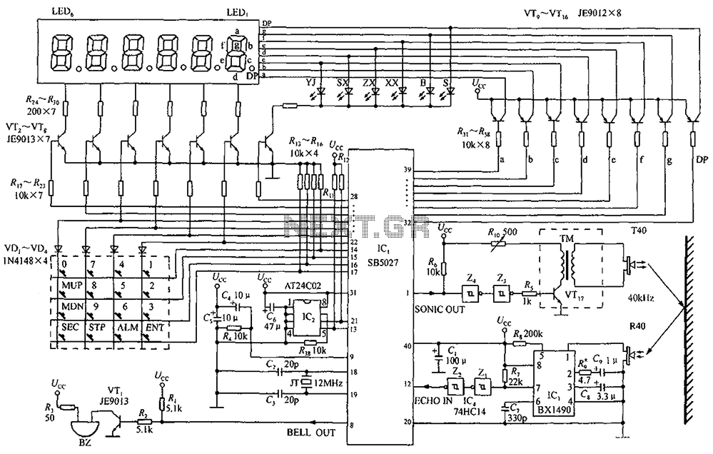
A circuit diagram of an ultrasonic range finder is constructed using a clock with a calendar and the Ultrasonic Ranging IC SB5027. The ultrasonic range finder circuit utilizes the Ultrasonic Ranging IC SB5027, which is designed to measure distances by...
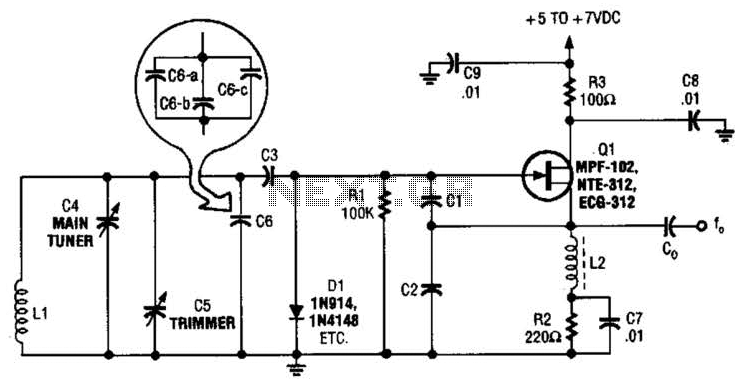
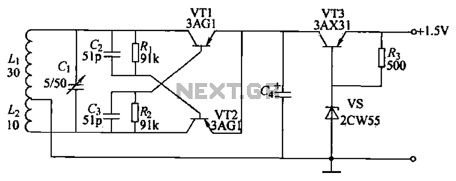
This basic VFO (Voltage Controlled Oscillator) operates within the 3 to 6 MHz frequency range and is commonly utilized in amateur radio applications, employing a Colpitts oscillator configuration. For operation at frequencies between 5 to 5.5 MHz, capacitors C2...
Maxim has introduced a series of five integrated oscillator building blocks in the MAX260x series, covering a frequency range of 45 to 650 MHz. The MAX2606 is designed for the VHF band, allowing frequency variation of approximately ±3 MHz...
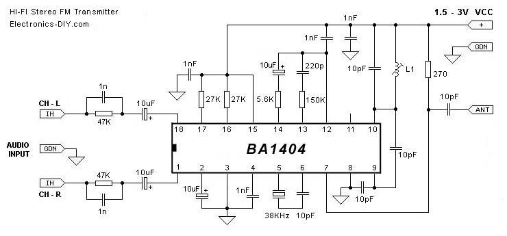
Children often go missing, causing immense suffering and economic losses for families. This situation also presents opportunities for unscrupulous child traffickers to exploit. To address this issue, a radio alarm system has been designed, which consists of a transmitter...
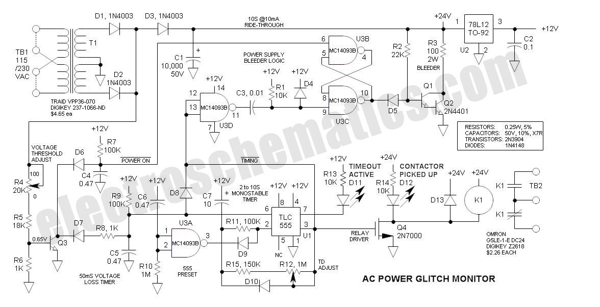
This AC Power Monitor continuously monitors the AC power line voltage for under-voltage conditions and missing cycles. When it detects a total of 5 or 6 consecutive anomalies, it triggers an alert. The AC Power Monitor is designed to provide...
The circuit depicted in Figure 3-170 illustrates a wound rotor induction motor operating at various speeds, with a voltage (turn difference frequency EMF) U induced in the rotor. The rotor open circuit voltage is represented as Uo (Us0). A...
Warning: include(partials/cookie-banner.php): Failed to open stream: Permission denied in /var/www/html/nextgr/view-circuit.php on line 713
Warning: include(): Failed opening 'partials/cookie-banner.php' for inclusion (include_path='.:/usr/share/php') in /var/www/html/nextgr/view-circuit.php on line 713