
Multi-point circuit diagram of a remote control switch
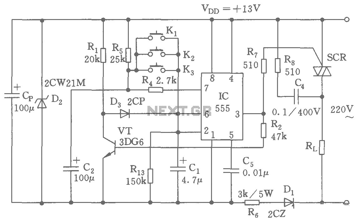
The circuit operates by first converting the AC input voltage to a regulated DC output using the buck rectifier. This rectifier is crucial for providing a stable 13V DC supply to the subsequent control circuitry. The 555 timer is configured in a bistable mode, allowing it to toggle between two states based on input signals from the switches (K1, K2, or Ks). The flip-flop behavior is established through the charging and discharging cycles of capacitors C1 and C2, influenced by the resistors R4, R5, and R13.
In the initial state, with C1 charged, the 555 timer is set to a high state. Pressing the control switch (K1, K2, or Ks) causes C1 to charge quickly, triggering a transition in the 555 timer. This transition generates a low output at pin 3, effectively turning off the SCR, which in turn cuts off the voltage to the load (VT). The feedback mechanism involving pin 6 of the 555 timer ensures that the circuit remains stable in its reset state until the next activation occurs.
This design allows for efficient control of electrical devices, providing the ability to turn them on or off remotely. The use of a thyristor for switching enhances the circuit's capacity to handle higher loads, making it suitable for various applications in automation and remote control systems. The careful selection of component values (R and C) determines the timing characteristics and responsiveness of the control circuit, allowing for customization based on specific requirements.As shown, the switching circuit comprises a buck rectifier circuit, the bistable trigger circuit and the thyristor control circuit. Implement remote control for electrical equipment turned on or off. Buck rectifier circuit provides the controller with a DC voltage of 13V. 555 and R5, R4, R13, C1, C2 and so flip-flop circuit. Just power, because the voltage on C1 is not mutation, 555 set, C2 through R5 charged to l2V. If you click this time K1 (K2 or Ks), C1 is quickly charged to a 2/3 VDD = 8V, 555 reset pin 3 referred to the low level, SCR off. Meanwhile, VT cut-off, 555 were 6 feet high, so that the reset 555 in a stable state. As then click K1 (K2 or Ks), and 555 is in the set state. So control K, can be realized on the electrical opening and closing control.
Related Circuits
This circuit can be integrated into a headlight switch to enable automatic switching between high and low beam headlights in the presence of oncoming traffic. It is a straightforward electronics project that includes a circuit diagram. The circuit operates by...
An exhaust fan is a crucial component in kitchens. This document presents a simple circuit designed to control kitchen fans by monitoring the ambient temperature. It is built around... The circuit for controlling an exhaust fan based on ambient temperature...
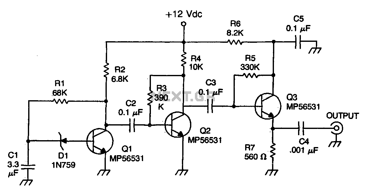
The Zener diode functions as an avalanche rectifier in reverse bias mode, connected to the input circuit of a wideband RF amplifier. The noise is amplified and subsequently applied to the cascade wideband amplifier, utilizing transistors Q2 and Q3. The...
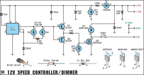
This circuit serves as a speed controller for a 12V motor with a continuous rating of up to 5A or as a dimmer for a 12V halogen or standard incandescent lamp rated up to 50W. It regulates power to...

12V Battery Charge Nominal Discharge (Low) Indicator Circuit. This circuit monitors car battery voltage and provides an indication of nominal supply voltage, as well as low or high voltage. The 12V Battery Charge Nominal Discharge Indicator Circuit is designed to...
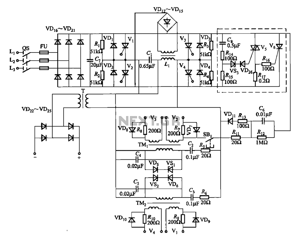
A 25kHz thyristor inverter welding machine circuit utilizes high-frequency operation to enable smaller transformer designs. The circuit diagram is illustrated in Figure 9-14. The no-load output voltage of the machine is 45V DC, with a peak voltage of 90V...