
electronic combination lock LS7220
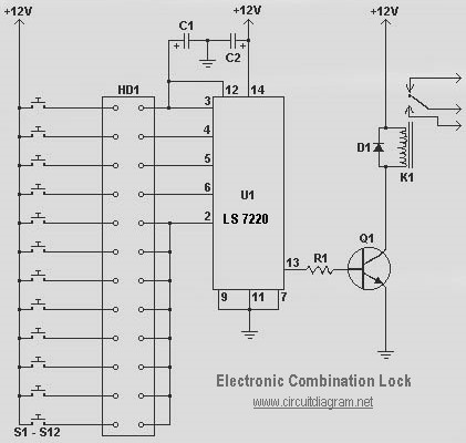
The electronic combination lock circuit utilizing the LS7220 IC is designed to enhance security by allowing access through a unique sequence of key presses. The LS7220 IC serves as the core processing unit, interpreting the input from the keypad. The capacitor C1 (1µF) is employed for decoupling, ensuring stable power supply to the IC, while C2 (220µF) provides additional filtering to smooth out voltage fluctuations. Resistor R1 (2.2K Ohm) is used to limit the current in the circuit, protecting sensitive components.
Transistor Q1 (2N3904 or 2N2222) functions as a switch, controlling the relay K1, which is the actuating component for the door lock mechanism. When the correct key combination is entered, the output from the LS7220 activates Q1, energizing the relay and allowing the door to be unlocked. Diode D1 (1N4148 or 1N4001-1N4007) is placed in parallel with the relay coil to prevent back EMF generated when the relay is de-energized from damaging other circuit components.
The NE555 timer circuit produces a siren-like sound, which can be integrated into the security system as an alarm feature. The NE555 timer is configured in astable mode, generating a square wave output at a frequency of approximately 300Hz. This frequency can be adjusted by varying the resistance and capacitance values connected to the timer. When the power supply is activated, the NE555 generates an audible tone, serving as an alarm signal when unauthorized access is attempted.
The short wave AM transmitter circuit operates at a fixed frequency of 12 MHz, which simplifies the design by eliminating the need for a tuned LC circuit. This transmitter can be used for various applications, such as remote control systems or simple communication setups. The circuit's simplicity makes it accessible for hobbyists and beginners in electronics, while still being effective for its intended purpose.The following diagram is a very easy and simple electronic combination lock based on IC LS7220. Component Part List: C1 = 1uF 25V C2 = 220uF 25V R1 = 2. 2K Ohm Q1 = 2N3904 / 2N2222 D1 = 1N4148 / 1N4001-1N4007 K1 = 12V SPDT Relay / Any appropriate relay with 12V coil U1 =. This is the circuit diagram electronic door lock security key system. It mea ns that this security system circuit is the combination of pressed key itself (not the mechanical), the output can be connected to drive the relay to open the door (usually using motor). It is a quite simple circuit of electronic door lock with. Here the circuit diagram of electronic siren based NE555. This circuit produces a sound like factory siren. It applies a 555 timer IC which is utilized as an astable multivibrator of a center frequency of about 300Hz.
The frequency is controlled by the pin 5 of the IC. When the power supply is switched ON, . Here the short wave AM Transmitter circuit design diagram. The circuit is quite simple and easy to build since it applies only a few electronic components. The primary feature of this transmitter is that it really is absolutely free from the LC (inductor, capacitor) tuned circuit and runs using a fixed frequency of 12 MHz. 🔗 External reference
Related Circuits
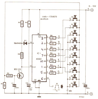
The cycle is repeated only when the S7 switch at the Q1 output is pressed within the designated time frame. When all keys are pressed in the correct order and within the specified time, Q7 goes high for approximately...

This liquid detector circuit diagram is designed using common electronic components. The liquid detector can activate an active buzzer to produce sound when a certain water level is reached. Since the water sensor and control circuit for the buzzer...
The circuit consists of a basic transistor switch with a relay connected at its collector as the load. This represents a straightforward electronic code lock circuit that employs a single transistor. The circuit operates by utilizing a transistor as a...
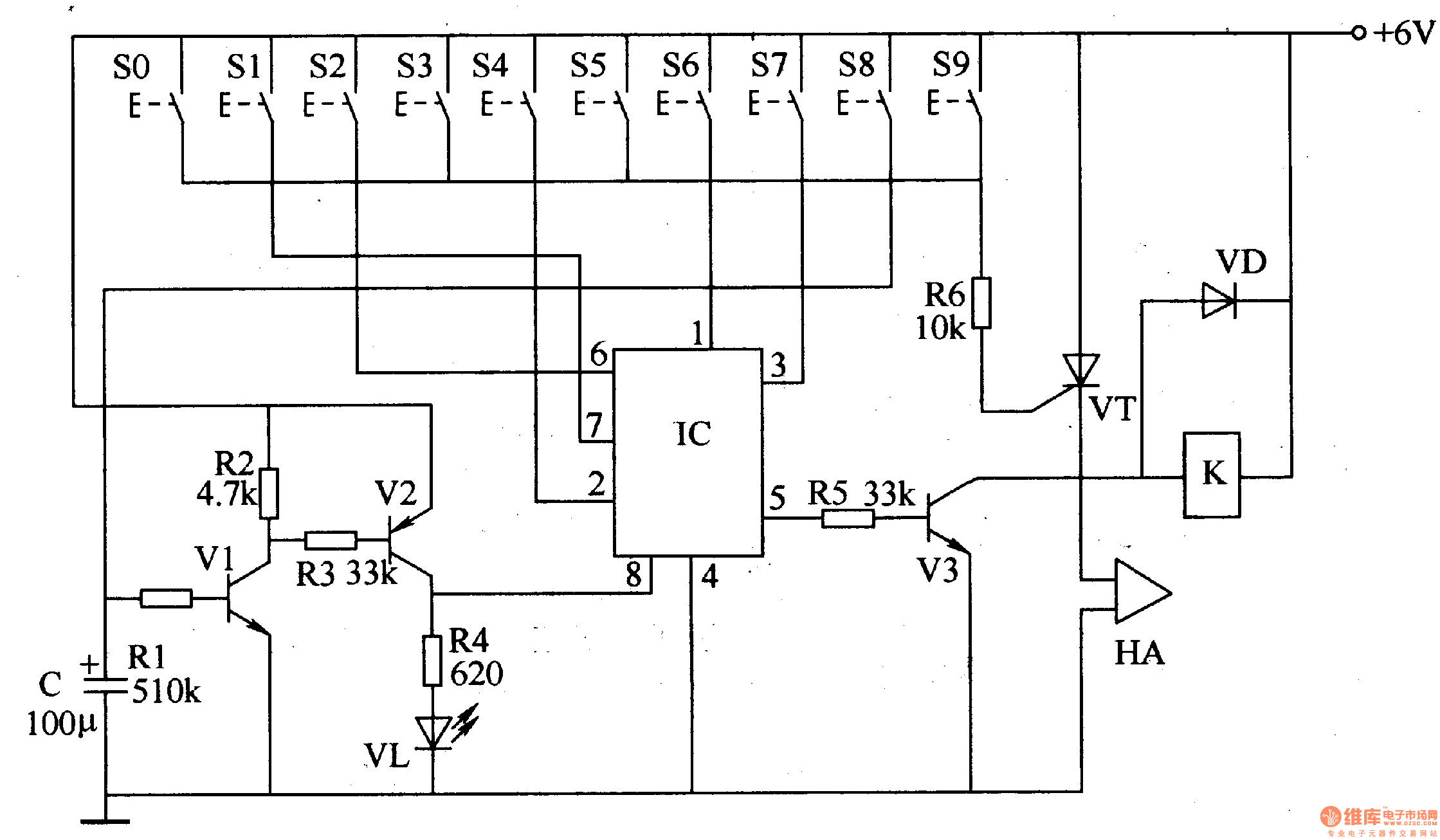
The digital lock circuit consists of a timing trigger circuit, a trick lock circuit, a sound and alarm circuit, and a control implementation circuit, as illustrated in Figure 3-101. The timing trigger circuit is made up of transistors V1...
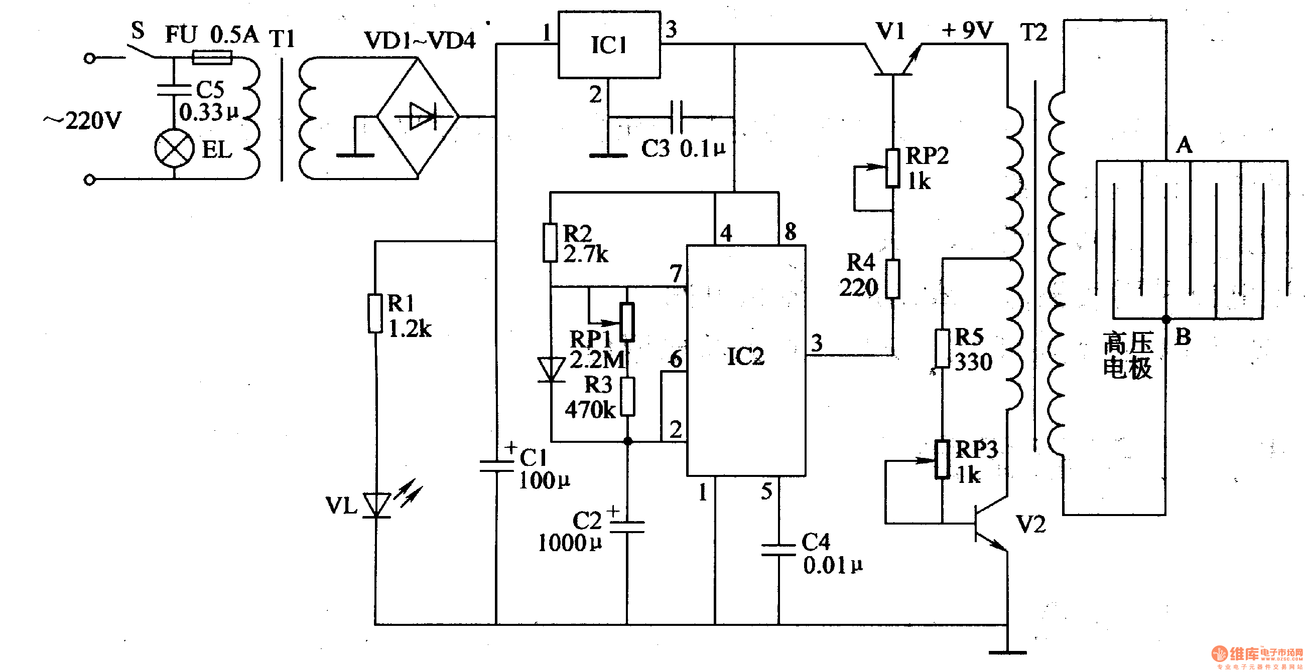
Working Principle: The circuit, as illustrated in figure 4-187, is composed of three main components: the power circuit, the pulse oscillator, and the high voltage generator. The power circuit includes components S, FU, TI, VD1-VD4, C1, C3, IC1, R1,...
A circuit is being designed to operate based on car locks, which receive a negative pulse to activate a latched relay, powering the ACC line that connects to a startup/shutdown controller. The current circuit configuration presents a challenge; to...