
555 Dream lantern control circuit diagram
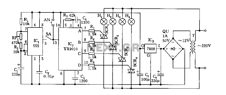
The circuit design incorporates a 555 timer (IC1) configured as an astable multivibrator, which generates a continuous square wave output. This output is utilized to control the light sequences through the YX9010 ASIC (IC2). The choice of resistors (R1, RP1, R2) and capacitor (C1) allows for precise tuning of the oscillation frequency, thus enabling a variety of lighting effects based on the desired ambiance. The inclusion of a manual switch provides user control, allowing for interactive experiences during events or celebrations.
In automatic mode, the circuit engages the thyristor trigger circuit, which allows for the control of higher power loads without significant heat generation, as the thyristors can handle large currents. This is crucial for applications where multiple lights are used simultaneously. The use of a triac with a minimum reverse breakdown voltage of 400V ensures reliability and safety in various operational conditions, accommodating different lighting setups.
Overall, this circuit is versatile and can be adapted for various decorative purposes, making it suitable for both personal and commercial use in festive environments. The combination of manual and automatic modes enhances usability, while the robust design ensures longevity and performance consistency.Fantasy lights, wonderful changes can be used to store, dance hall or family holiday decorations. Its control circuit is shown. Lantern multivibrator control circuit, a control circuit and thyristor trigger circuit and step-down power supply circuit. AC step-down rectifier circuit is IC1, IC2 provides + DC voltage of 9V. IC2 use lights control ASIC YX9010, its memory chip has eight lights control. This manifold peripheral circuit is very simple. It can be controlled manually or automatically. AN manual switch, every press time, the display lights transform a program can be realized four lights all light, fast forward and slow cycle flash, fast flash and slow cycle backward forward transformed flash and so on. SA automatic mode switch, it will be 3 feet of IC1 output contact (closed), automatic conversion and control lantern.
IC1 (555) and R1, RP1, R2, C1, etc. to form a multi-harmonic oscillator, its oscillation period T 0.693 (R1 + 2R2 + RP1) C1 Period of oscillation parameters given in illustration is from 5 to 76 seconds, the duty cycle is close to 1: multivibrator pulse 1.IC1 added to the IC2 output control mode switch terminal 13 feet, each time to a high level, special lights IC2s output of a, B, C, D state transition time. With no steady-state circuitry constantly flip, flash lights and color patterns are constantly turned over, again and again followed by conversion to produce fantastic results.
Circuit thyristor power according to the load size selected lights, optional 3CTS-1A, 3CTS-3A, SCTS-5A, require not less than the reverse breakdown voltage of 400V (D grade) triac.
Related Circuits
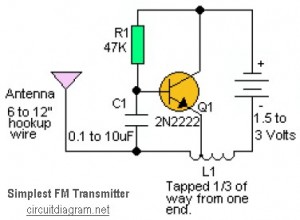
This is likely the simplest radio transmitter available, consisting of five components and capable of being assembled in a compact space. It is suitable for science fair projects or other science-related endeavors where short-range transmission is beneficial. The device...

A dual audio amplifier that delivers 50 W per channel is illustrated in the schematic. It features a preamplifier and tone controls, as well as a headphone amplifier. The circuit also shows a power supply providing 38.5 V and...
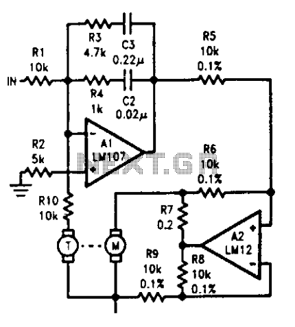
The tachometer, mounted on the same shaft as the DC motor, functions as a generator, producing a DC output voltage that is proportional to the motor's speed. A summing amplifier, labeled as Al, manages its output to ensure that...
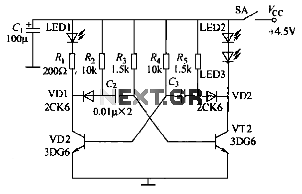
The infrared transmitter circuit, as depicted in Figure 18-la, utilizes transistors VT1 and VT2 along with RC components to create an astable multivibrator. The circuit operates with VT1 and VT2 receiving base bias from resistors, and closing switch SA...
There are two independent modeling light circuits for the P2000D, one for each of the two channels. The modeling light circuit is completely separate from the high voltage strobe circuitry, even featuring its own On/Off switch. Therefore, the functionality...
Thanks to the S6986, the circuit is very simple and requires few components. D2, D3, D5 and D6 forms a bridge rectifier allowing to plug the sensor connector brick in any direction. C1 filters power supply, it must be...