
555 electronic musical instrument additional combo audio circuit

The combination audio circuit integrates an astable multivibrator configuration utilizing the 555 timer IC, which is a widely used component in timing applications. The astable multivibrator operates continuously, generating a square wave output that can be used to trigger audio signals corresponding to drum and cymbal sounds.
In this setup, R1, RP1, and R2 are resistors that determine the frequency of the oscillation, while C1 is a capacitor that influences the timing characteristics of the output waveform. The values of these components can be adjusted to modify the tempo and rhythm of the generated sound, allowing for flexibility in performance.
The output from the 555 timer can be connected to a sound synthesis module or a digital audio processor that generates the desired drum and cymbal sounds. By adjusting the duty cycle of the square wave, the audio circuit can create varied sound dynamics, enhancing the expressiveness of the musical performance.
Additionally, the implementation of this audio circuit can involve further components such as operational amplifiers for signal conditioning, filters to refine the audio output, and possibly a mixer stage to balance the levels of the drum and cymbal sounds. This comprehensive approach ensures that the audio output is not only synchronized with the rhythm generator but also meets the quality expectations of contemporary electronic music performance.If we add this combo audio circuit (as the figure 14-38 shows) to the automatic rhythm generator of the electronic musical instruments, we can meet the the requirements of players to add the combo audio of drum and cymbals to make the performance effect more perfect. As the figure shows, the astable multivibrator is composed of the 555 and R1, RP1, R2, C1,.. 🔗 External reference
Related Circuits
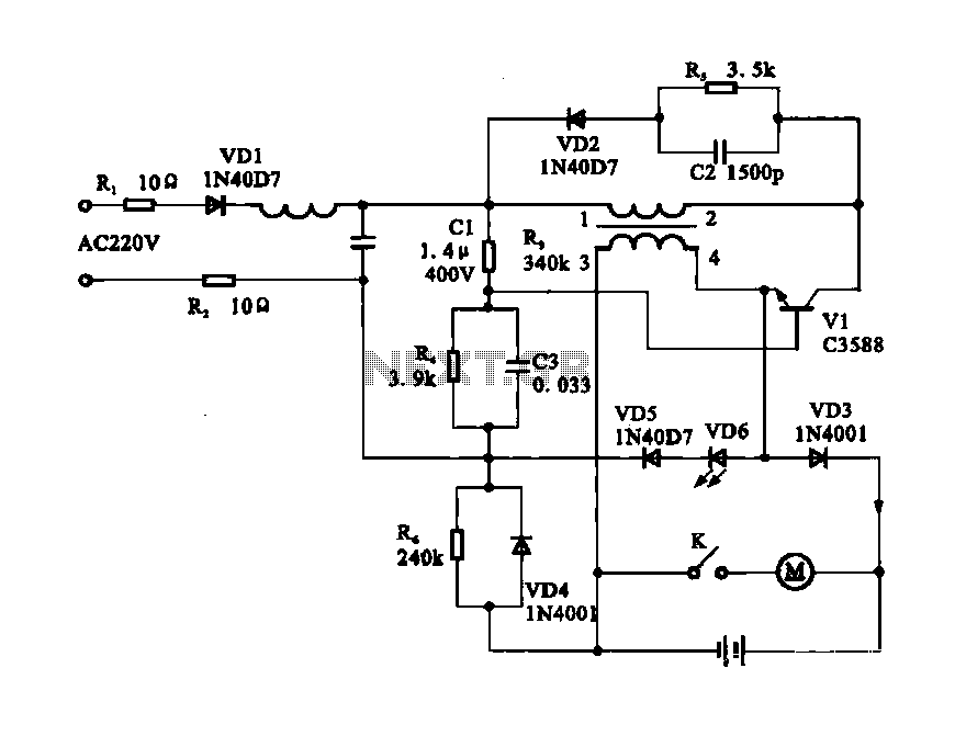
Electric shaver motor drive circuit. It illustrates a typical motor drive circuit for an electric shaver. AC 220V is used to charge the battery through the charging circuit, which also provides power to the motor. After activating the charge-on...

The high-temperature alarm will emit a beep and the LED will blink when the temperature of the device rises abnormally. This simple overheating alarm is designed to monitor heat levels. The high-temperature alarm circuit is an essential safety device used...
A touch sensor relaxation oscillator is utilized in the hysteresis lab. In this schematic, the variable capacitor is represented by a person's finger and a touch plate made from aluminum foil and packing tape. Code was developed for the...
A simple whole house FM transmitter circuit diagram and description. Operating power is a 1.5V battery of any type. This circuit is able to transmit at a distance of 30 meters. The whole house FM transmitter circuit operates on a...

The circuit SJT is a 1024 kHz warming crystal oscillator. The circuit is illustrated in the accompanying chart. Due to the low output signal level, a transistor (VT1) is employed as a buffer amplifier. The base bias resistor (R2)...

A lithium-ion battery charging circuit is illustrated above. Initially, when charging begins, if the battery voltage is below 8.4V, the output of IC1 is inactive. As a result, Q2 remains off, and the LM317 operates in constant current mode....