
High Temperature Alarm Circuit

The high-temperature alarm circuit is an essential safety device used to detect abnormal temperature increases in electronic equipment or environments. The core components of this circuit typically include a temperature sensor, a microcontroller or comparator, an audible alarm (buzzer), and an LED indicator.
The temperature sensor, often a thermistor or an LM35 integrated circuit, continuously monitors the ambient temperature. When the temperature exceeds a predefined threshold, the sensor outputs a signal to the microcontroller or comparator. The microcontroller is programmed to interpret this signal and determine if the temperature is beyond acceptable limits.
Upon detecting an over-temperature condition, the microcontroller activates an audible alarm, usually a piezo buzzer, which emits a beeping sound to alert users of the potential overheating situation. Simultaneously, the microcontroller also triggers an LED to blink, providing a visual indication of the alarm condition. The blinking LED serves as an immediate visual cue that can be observed from a distance.
The circuit can be powered by a standard DC power source, and it may include additional features such as a reset button to silence the alarm and reset the system. Proper placement of the temperature sensor is critical to ensure accurate readings, and it should be positioned in a location that reflects the temperature of the device or environment being monitored.
In summary, this high-temperature alarm circuit is a straightforward yet effective solution for monitoring temperature and providing alerts to prevent overheating, thereby enhancing the safety and reliability of electronic devices.The high temperature alarm will beep and LED blinks when the temperature of the device increases abnormally. This simple over heat alarm is to monitor heat.. 🔗 External reference
Related Circuits
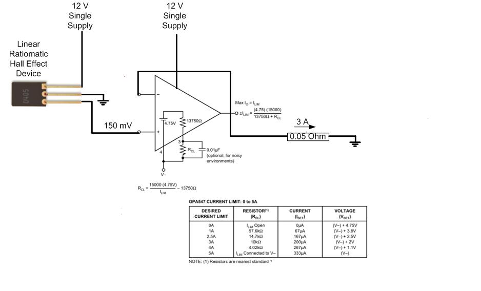
The proposed approach would dissipate (12V)(3A) = 36 watts, which results in significant heat generation in the circuit. This necessitates consideration of two alternatives: 1) Operating the op-amp at a lower supply voltage, if feasible, or 2) Utilizing a...
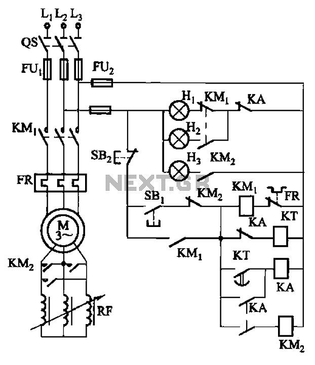
The circuit depicted in Figure 3-165 utilizes a time relay (KT) for controlling the start-up time. Indicator light Hi serves as the power indicator, H2 is designated for the start lights, and H3 functions as the running lights. The circuit...
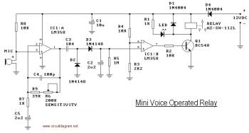
This circuit diagram illustrates a voice-operated relay, which functions similarly to a sound-activated switch circuit. It activates and deactivates the switch based on sound input. The output switch of this circuit is controlled by a relay. The release time...
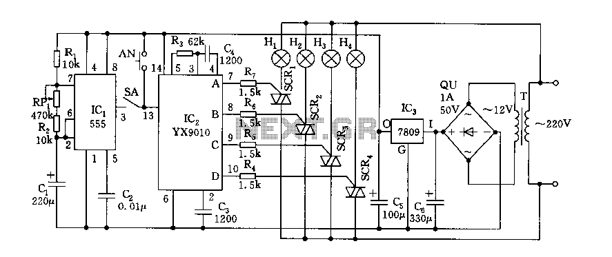
Fantasy lights offer wonderful changes suitable for storage, dance halls, or family holiday decorations. The control circuit is depicted here, which includes a multivibrator control circuit, a thyristor trigger circuit, and a step-down power supply circuit. The AC step-down...

Recently, the Overunity and Energetics online forums, which serve as significant platforms for members of the Open Source and Free Energy communities, have been discussing a remarkable phenomenon known as the Rosemary Ainslie Circuit. This circuit is named after...
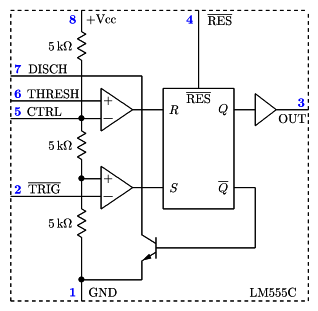
It is a typical Astable Multivibrator (AMV) setup. The capacitor charges through both resistors until it reaches 2/3 of Vcc, which is the level of the internal comparator. This triggers a flip-flop, activating the Discharge output (DIS). The capacitor...