
PIC Stepper Motor Tester
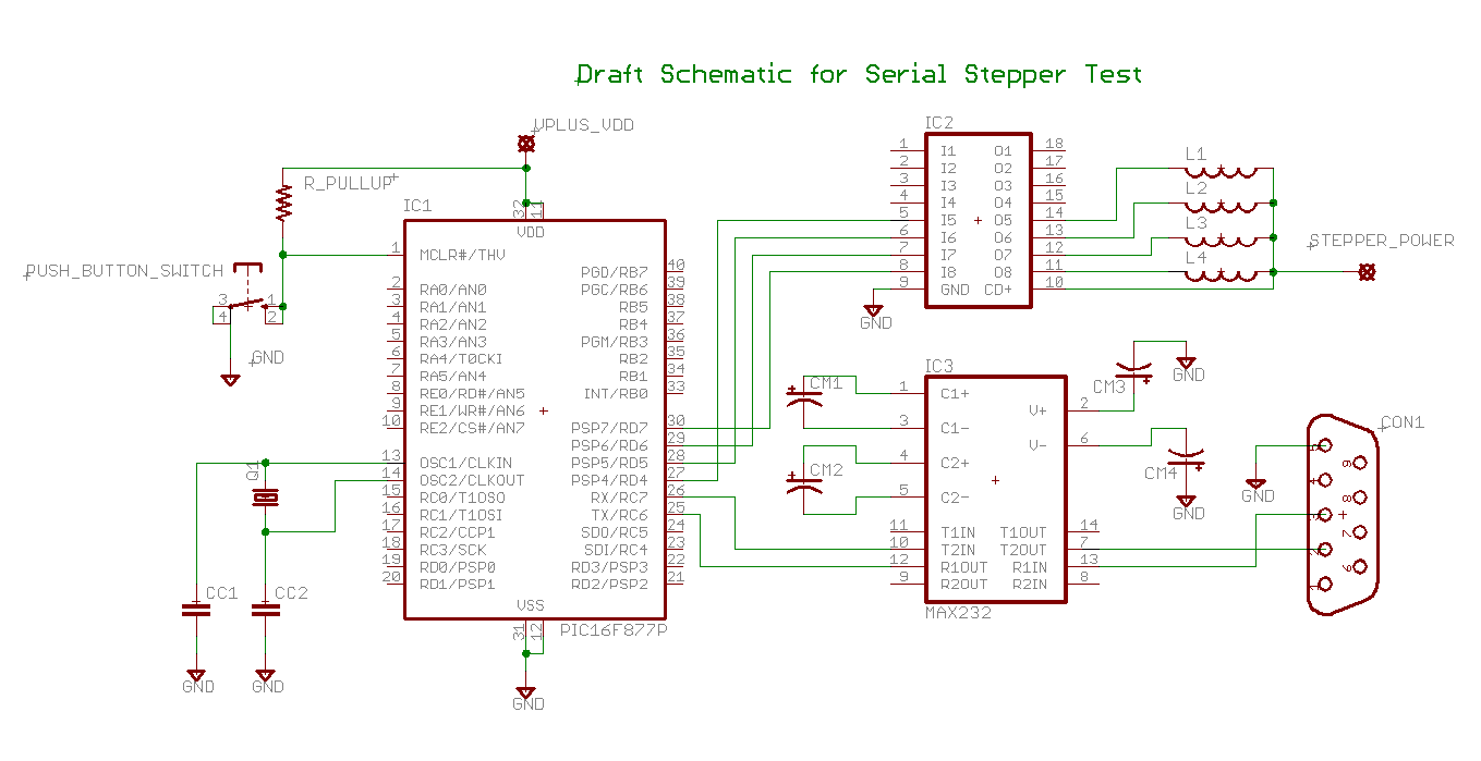
The circuit design described involves several key components and connections that facilitate control of a unipolar stepper motor. The PIC16F877A serves as the central processing unit, executing commands received from a PC via RS232 communication, facilitated by the MAX232 level shifter. This allows for proper voltage level translation between the microcontroller and the PC.
The motor control is achieved through the ULN2003 driver, which interfaces with the stepper motor windings. Each winding is controlled by a low-side switch configuration provided by the ULN2803, which ensures that the current flow through the motor windings is effectively managed. The choice of using Darlington transistors in the ULN2803 allows for high current handling capability, making it suitable for driving motors with significant power requirements.
The microcontroller operates at a 5V supply, while the motor can be powered with higher voltage levels, adhering to the specifications of the ULN2803 and the stepper motor’s ratings. This setup provides flexibility in terms of motor performance, allowing for higher torque and speed when required.
The command interface, while straightforward, requires careful handling to avoid program crashes due to invalid parameters. The use of carriage returns to terminate commands ensures that the microcontroller can properly parse and execute the received instructions. Additionally, the inclusion of pull-up or pull-down resistors on uncommitted I/O lines enhances the robustness of the circuit by preventing floating inputs.
For users seeking to implement similar projects, the provided zip file contains all necessary source code, which can be modified and compiled using the BoostC compiler. The option to utilize a Java program instead of a terminal emulator for command input can further streamline the user experience and reduce the likelihood of input errors.
Overall, this schematic illustrates a practical approach to controlling a unipolar stepper motor using a microcontroller, emphasizing the importance of component selection, power management, and user interface design for effective operation.Determining which drive wire is which on a unipolar stepper motor. This is the type of motor that I have most commonly found surplus or in salvage equipment Platform: PIC16F877A using BoostC connected via rs232 to a PC running a terminal program. The PIC chip is supplemented with a MAX232 chip and a ULN2003 driver. I have used a PIC 16F877A for the project, but pretty much any PIC with a uart and another 4 free I/O lines should do. To increase the drive to the motor I used a ULN2803 which is simply an array of Darlington transistors and diodes to be used as a low side switch for each motor winding. There are other similar chips around or discrete devices can be used. I run the pic, on 5 volts, and a larger voltages for the stepper, up to the limit of the driver. ( the UNL2803 is good for 50 v at. 5 amp as a switch ) and the rating of the stepper motor. If you have a high power motor you may want a driver with more guts, Just put in some substitute. Coil drive is on or off there is no PWM involved here. Note that the hardware has substantial uncommitted resources. You could easily drive another motor for example. Also some of you may want to put some pull up or down resistors on some of the uncommitted resources.
Instead of this board you could use the circuit from the PIC based Stepper Motor Dancing Analog Clock, the main difference is that that circuit does not use the MAX232 chip, it relies on an off board level shifter ( makes it easy to shift the level shifter from project to project while saving some money and board space ) All commands ( except stop should be terminated with a carriage return ) Note that the command interface is not very smart, giving parameters that are out of range my blow the whole program up. If so reboot the PIC. Do not send a new command ( except stop ) until earlier commands have been completed ( actually you can get ahead some if you are careful ).
In earlier versions the commands had to be in lower case, I think current versions take either upper or lower case - check it out. I no longer have the patience for assembly language. I have moved on to C in particularly BoostC, see link below. I like this compiler it has both a free version with some restrictions and a very reasonably priced full version.
Writing in C should make the program fairly easy to read. Most of the design should be evident by reading the program, however a few notes here may help. see: Stepper Motor Demonstration and Tester for comments that apply to both the PIC and Arduino versions of the project. The zip file contains the entire source bootst project. Unzip into a directory and open in source boost. Set the target to 16F877A and change the linker options ( Settings -> options -> linker
After compiling my compiler reports something like: Rather than use a terminal emulation program you can use a Java Program. This makes it easier to issue commands and has a much lower chance of making a mistake. The interface looks like this: ( actually almost written, email me if you have a special interest ). 🔗 External reference
Related Circuits
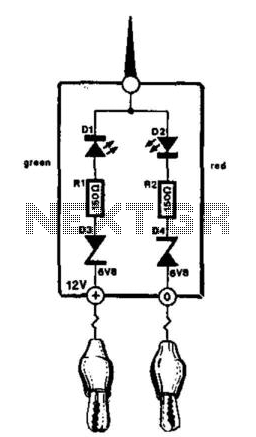
This compact tester is designed for checking vehicle electrical circuits. Two LEDs indicate whether one of the clips is connected to the positive supply line (red) or to ground (green). The unit is powered by the vehicle battery. It...
PWM is a device that can be utilized as an efficient light dimmer or DC motor speed controller. Function: for a general-purpose device that can... PWM (Pulse Width Modulation) is a versatile technique widely employed in various electronic applications, particularly...
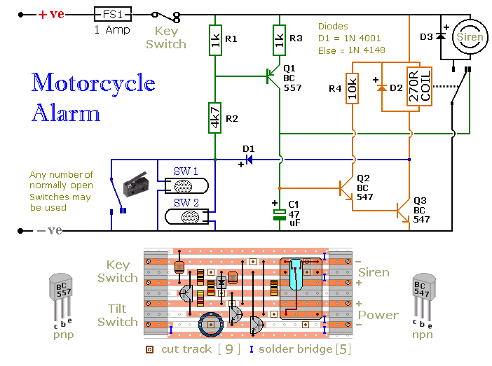
The circuit board and switches require protection from environmental factors, as moisture or condensation can lead to malfunctions. The board is compact without its terminal blocks. It is advisable to select a siren that has sufficient internal space for...
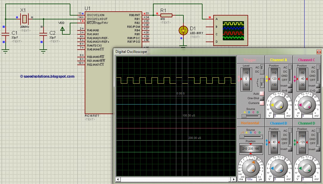
Attached are three captures from a L297/L298 board using the same motor at 500, 750, and 900 steps per second on a 36V supply, wired in bipolar parallel (coil resistance = 3.2 ohms). This shows the A-enable signal (blue)...
This tutorial on the PIC16F877 microcontroller addresses the question of how to utilize Timer0 and manage its interrupts. It utilizes the PIC16 simulator for demonstration purposes. The PIC16F877 microcontroller is a versatile device widely used in embedded systems. Timer0 is...
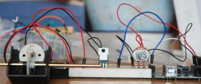
A quick circuit showing how to control the speed of a DC motor with a potentiometer with your Arduino board. Also shows how to use a TIP120 transistor to allow the Arduino control a larger power supply. This circuit utilizes...