
High Speed Photography circuit
Relay
A relay is an electromagnetic device. It used a small electromagnet to mechanically close a pair of switch contacts. They have the advantage that the circuit that controls the electromagnet and the circuit involving the switch are electrically separate. Relays are commonly used in automotive applications to switch on a large current with a much smaller current in the electromagnet. Their primary disadvantage is that they respond very slowly, and therefore they are not ideally suited to the task of firing the flash for HSP. However, they are very useful for other applications in more complex HSP control systems. Relays are also relatively expensive (as far as electronics goes).
Transistor
A much faster switch can be created from a bipolar transistor. These three terminal (leg) devices allow current to flow between two of the terminals (collector and emitter) when a much smaller current is flowing from the third terminal (base) to the emitter. Effectively, a signal sent to the base of an NPN transistor can create a closed switch between the emitter and collector. The correct choice of transistor depends on the voltages that will be placed across the terminals, and the current that is to flow through the circuit. This is a rather narrow and oversimplified view of the transistor. For the inexperienced that wish to depart from the examples circuits here, or in the links, consult a suitable electronics reference (The Art of Electronics, by Horowitz and Hill would be a good choice). The greatly reduced response time of the transistor comes at the expense of polarity and coupled circuits. This means the direction that current is to flow through the device is important, and that the electronics on the switch side and control side of the transistor are connected together.
For many flash guns (our primary concern here), the voltage across the terminals that must be closed to fire the flash is quite high (typically 300V). Unfortunately, transistors are not normally suitable for such high voltages. We therefore recommend that a transistor is not used to operate the flash unless you are certain that the transistor specifications are appropriate for the flash terminal voltage. In general, transistors will be an essential element in other HSP control system applications.
Silicon Controlled Rectifier (SCR)
An SCR is an extension of the bipolar transistor, with a few peculiar properties. Firstly, it capable of switching high voltages (400V SCRs are sufficient for commercial flash guns). Secondly, once an SCR has been switched on by the control signal, it does not switch off again until the supply voltage (being switched) drops to almost zero. For a flash, this means the switch stays on until the flash has fully discharged. Like the bipolar transistor, the SCR is a three terminal device and it is polarised. The terminals are called the source, drain and the gate. Current will flow from the source to the drain when the gate voltage is raised about 1V above the drain. An SCR would typically be used for the flash gun only.
In its simplest form, the HSP control system can be thought of as the three separate modules described in the electronics section (Input, Time delay and Control). The "stand alone" electronics approach sees these modules constructed in electronics hardware. A personal computer provides a software alternative for the time delay module, and a flexible platform for binding together many other modules. This still requires the construction of electronics hardware for input signals and control signals, though the modules can be made simpler than their "stand alone" counterparts. However, the gains made by simplifying the electronics are offset by the requirement that software must be written to implement the core of the HSP control system. The advantage of software implementation is the ease with which changes can be made to improve the system, and correct mistakes. It also provides a platform for development.
Since the input and control signal modules must still be constructed from electronic circuit, a method for coupling these components to the electronic circuitry of the PC is required. There are a variety of methods available, though the parallel port is arguably the simplest and most effective interface.
Parallel Port
The parallel port provides a simple, yet versatile means of interfacing small electronic devices with a PC. Although use of this port has long been the domain of the printer, it can accommodate a wide variety of other devices, including an HSP I/O device.
Although different implementations of the parallel port provide slightly different functionality, a "common to all" approach to the parallel port can be taken. For a detailed discussion of the parallel port, consult one of the references in the links page.
The parallel port is composed of three ports - DATA, STATUS, and CONTROL. The byte written to or read from these ports sets or observes the digital state of the signal lines with which they are associated. The DATA port is an output port with 8 signal lines, and the address of the port is the base address of the parallel port. The CONTROL port is also an output port, though there are only 4 external signal lines. The base address of the CONTROL port is the base address + 1. The STATUS port is an input port with 5 external lines, and one of these has a dual function. The address is the base address + 2. All of the external signal lines are accessed via a D25 pin plug. Signal ground lines are also accessible via the D25 plug. The digital state of each output control line is determined by the state of 1 bit in the corresponding port. For example, pin 4 on the D25 plug corresponds to bit 2 of the DATA port. If the byte written to the base address of the parallel port has bit 2 set to 1, then the output state of line 4 is high, or approximately +5V. Alternatively, if the bit was set to 0, the line output state would be low, or approximately 0V. Some of the signal lines in the CONTROL port are inverted. This means if the corresponding bit is 1, the output state is low, and if the bit were 0, the output state would be high. Inverted or not, the output lines of the DATA and CONTROL ports provide 12 digital signal lines, the states of which can be controlled separately by software. The details of electrical connection to these lines will be treated in a later section.
The STATUS port provides 5 lines onto the I/O bus of the PC. The software approach to the input signal lines is simply to read the byte in the port. Each bit in the byte held in the STATUS port, corresponding to an input line, is dependent on the digital state of the input line. Again, some of the input lines are inverted, so that the relation between electrical state and the corresponding bit depends on the particular line. Either way, the state of 5 independent input signals can be determined with software. Again, electrical connection to the input lines of the STATUS port shall be treated in a later section.
The DATA and CONTROL ports are both latched. This means the output signals are set when a software operation writes a byte to the port, and the output remains unchanged while other software operations are performed.
Electrical connection to the parallel port is relatively straightforward for both input and output lines, though a few simple rules must be exercised. The output lines on a parallel port (DATA and CONTROL) are TTL (transistor-transistor logic) and are capable of sourcing about 2.5mA or sinking about 20mA. The choice between sourcing or sinking current to drive a load is dependent on the load, though sinking current is the favoured method. The primary difference is the requirement for an external power supply, though one is usually required anyway. When sourcing current from the TTL output lines, power to drive the load is supplied from the port when the line is in the HIGH state. When sinking current, power to drive the load is provided by an external +5V supply, and current flows through the load when the output line is in the LOW state. Electrical connection to input lines is a little more tricky. The parallel port is connected to the I/O bus, which means that many devices have a common link to the CPU. To ensure that input from different devices do not interfere and overload the bus, each device must be able to decouple its signals from the bus. For input lines, this can be done in one of two ways - tri-state drivers or open collector transistors. Tri-state drivers are commonly used in commercial devices, but open collector transistors are a simpler alternative. The collector of an NPN transistor is connected to the input line, the emitter is connected to ground, and the input signal drives the base (through an appropriate resistive load). When the input signal to the base is low, the transistor will not conduct between the collector and emitter, and the transistor is said to be in an open state.
The previous section was concerned with switching on the flash gun in response to a control signal. However, the devices described can be applied to control a variety of other components. For example, it may also be necessary for the control system to open the camera shutter and turn on and off a motor or electromagnet. The choice of control device should take into consideration the required timing precision as well as the current and voltage specifications of the device.
Input Signals
In order to construct a closed loop control system, some form of input device to provide feedback is required. In precise positioning control systems, a wide range of values can be measured and used as feedback. In simple HSP systems, input signals are typically used as a trigger for a binary control system (i.e., the flash gun control signal is turned on when a noise is detected or an IR beam is broken). This can often be broken down into three separate pieces. The first is the transducer, which provides an electrical signal in response to its environment. The second stage is amplification, which boosts the usually feeble signal from the transducer. The third stage is comparison, which produces the control signal if the amplified input signal is above (or below) a preset threshold.
Time Delays
It is rare that the flash gun should be fired at the instant the input device produces the triggering signal. Therefore, a short and precise time delay is required. A simple electronic time delay unit should have an input, an output, and a means for presetting the delay time. When the input signal changes, the output signal will change to match the input signal after the time delay. This kind of device could be constructed using either digital or analogue electronics techniques. The commercially available 555 timer chip is probably the simplest method for stand-alone HSP systems. Since the 555 chip has digital inputs and outputs, the control signal issued by the input electronics should be 0V for the off state and +5V for the on state. Similarly, the flash should fire when the control signal goes from 0V to +5V.Simple electronics provides the foundation for many closed loop control systems. Since the principle components that we would wish to control for HSP are electronic in nature, an electronic control system is the natural choice. As this document is not designed to be a course in electronics, only general concepts shall be presented, and our system as an example.
The choice of available power supply should be considered before designing circuits. Old personal computers are a great source of cheap yet versatile power supply units. These will usually provide terminal voltages at -12V, 0V (GND), +5V and +12V. This will allow the use of dual rail operational amplifiers, digital logic devices (TTL and CMOS) along with the traditional single component devices (transistors, relays, SCRs etc.). Less versatile alternatives are batteries and +12V transformers. Once a power supply has been selected, your attention can turn to the functions you want your control system to exhibit.
The basic requirement of any HSP control system is the ability to fire the flash gun. The electronics required to do this may depend on the particular flash gun you have, so some experimentation may be required. For all flash guns, the flash is fired by closing a switch. Although this seems very straight forward, we need this switch to close when given an electrical signal.
There are (at least) three devices that can operate a "switch" is response to another electrical signal. We consider each in turn. Relay A relay is an electromagnetic device. It used a small electromagnet to mechanically close a pair of switch contacts. They have the advantage that the circuit that controls the electromagnet and the circuit involving the switch are electrically separate.
Relays are commonly used in automotive applications to switch on a large current with a much smaller current in the electromagnet. Their primary disadvantage is that they respond very slowly, and therefore they are not ideally suited to the task of firing the flash for HSP.
However, they are very useful for other applications in more complex HSP control systems. Relays are also relatively expensive ( as far as electronics goes ). Transistor A much faster switch can be created from a bipolar transistor. These three terminal (leg) devices allow current to flow between two of the terminals (collector and emitter) when a much smaller current is flowing from the third terminal (base) to the emitter. Effectively, a signal sent to the base of an NPN transistor can create a closed switch between the emitter and collector.
The correct choice of transistor depends on the voltages that will be placed across the terminals, and the current that is to flow through the circuit. This is a rather narrow and oversimplified view of the transistor. For the inexperienced that wish to depart from the examples circuits here, or in the links, consult a suitable electronics reference (The Art of Electronics, by Horowitz and Hill would be a good choice).
The greatly reduced response time of the transistor comes at the expense of polarity and coupled circuits. This means the direction that current is to flow through the device is important, and that the electronics on the switch side and control side of the transistor are connected together.
For many flash guns (our primary concern here), the voltage across the terminals that must be closed to fire the flash is quite high (typically 300V). Unfortunately, transistors are not normally suitable for such high voltages. We therefore recommend that a transistor is not used to operate the flash unless you are certain that the transistor specifications are appropriate for the flash terminal voltage.
In general, transistors will be an essential element in other HSP control system applications. Silicon Controlled Rectifier (SCR) An SCR is an extension of the bipolar transistor, with a few peculiar properties. Firstly, it capable of switching high voltages (400V SCRs are sufficient for commercial flash guns). Secondly, once an SCR has been switched on by the control signal, it does not switch off again until the supply voltage (being switched) drops to almost zero.
For a flash, this means the switch stay on until the flash has fully discharged. Like the bipolar transistor, the SCR is a three terminal device and it is polarised. The terminals are called the source, drain and the gate. Current will flow from the source to the drain when the gate voltage is raised about 1V above the drain. An SCR would typically be used for the flash gun only. In it's simplest form, the HSP control system can be thought of as the three separate modules described in the electronics section (Input,Time delay and Control).
The "stand alone" electronics approach sees these modules constructed in electronics hardware. A personal computer provides a software alternative for the time delay module, and a flexible platform for binding together many other modules. This still requires the construction of electronics hardware for input signals and control signals, though the modules can be made simpler than their "stand alone" counterparts.
However, the gains made by simplifying the electronics are offset by the requirement that software must be written to implement the core of the HSP control system. The advantage of software implementation is the ease with which changes can be made to improve the system, and correct mistakes.
It also provides a platform for developement. Since the input and control signal modules must still be constructed from electronic circuit, we need a method for coupling these components to the electronic circuitry of the PC. There are a variety of methods available, though the parallel port is arguably the simplest and most effective interface.
Parallel Port The parallel port provides a simple, yet versatile means of interfacing small electronic devices with a PC. Although use of this port has long been the domain of the printer, it can accommodate a wide variety of other devices, including a HSP I/O device.
Although different implementations of the parallel port provide slightly different functionality, we shall take the "common to all" approach to the parallel port. For a detailed discussion of the parallel port, consult one of the references in the links page. The parallel port is in fact composed of three ports - DATA, STATUS and CONTROL. The byte written to or read from these ports sets or observes the digital state of the signal lines with which they are associated.
The DATA port is an output port with 8 signal lines, and the address of the port is the base address of the parallel port. The CONTROL port is also an output port, though there are only 4 external signal lines. The base address of the CONTROL port is the the base address + 1. The STATUS port is an input port with 5 external lines, and one of these has a dual function. The address is the base address + 2. All of the external signal lines are accessed via a D25 pin plug. Signal ground lines are also accessible via the D25 plug. The digital state of each output control line is determined by the state of 1 bit in the corresponding port.
For example, pin 4 on the D25 plug corresponds to bit 2 of the DATA port. If the byte written to the base address of the parallel port has bit 2 set to 1, then the output state of line 4 is high, or approximately +5V. Alternatively, if the bit was set to 0, the line output state would be low, or approximately 0V. Some of the signal lines in the CONTROL port are inverted. This means if the corresponding bit is 1, the output state is low, and if the bit were 0, the output state would be high.
Inverted or not, the output lines of the DATA and CONTROL ports provide 12 digital signal lines, the states of which can be controlled separately by software. The details of electrical connection to these line will be treated in a later section. The STATUS port provides 5 lines onto the I/O bus of the PC. The software approach to the input signal lines is simply to read the byte in the port. Each bit in the byte held in the STATUS port, corresponding to an input line, is dependent on the digital state of the input line.
Again, some of the input lines are inverted, so that the relation between electrical state, and the corresponding bit depends on the particular line. Either way, we can determine the state of 5 independent input signals with software. Again, electrical connection to the input lines of the STATUS port shall be treated in a later section.
The DATA and CONTROL ports are both latched. This means the output signals are set when a software operation writes a byte to the port, and the output remains unchanged while other software operations are performed. Electrical connection to the parallel port is relatively straight forward for both input and output lines, though a few simple rules must be exercised.
The output lines on a parallel port (DATA and CONTROL) are TTL (transistor- transistor logic) and are capable of sourcing about 2.5mA or sinking about 20mA. The choice between sourcing or sinking current to drive a load is dependent on the load, though sinking current is the favoured method.
The primary difference is the requirement for an external power supply, though one is usually required anyway. When sourcing current from the TTL output lines, power to drive the load is supplied from the port when the line is in the HIGH state.
When sinking current, power to drive the load is provided by an external +5V supply, and current flows through the load when the output line is in the LOW state. Electrical connection to input lines is a little more tricky. The parallel port is connected to the I/O bus, which means that many devices have a common link to the CPU.
To ensure that input from different devices do not interfere and overload the bus, each device must be able to decouple its signals from the bus. For input lines, this can be done in one of two ways - tri-state drivers or open collector transistors.
Tri-state drivers are commonly used in commercial devices, but open collector transistors are a simpler alternative. The collector of an NPN transistor is connected to the input line, the emitter is connected to ground, and the input signal drives the base (through an appropriate resistive load).
When the input signal to the base is low, the transistor will not conduct between the collector and emitter, and the transistor is said to be in an open state. The previous section was concerned with switching on the flash gun in response to a control signal. However, the devices described can be applied to control a variety of other components. For example, we may also want the control system to open the camera shutter and turn on and off a motor or electromagnet.
The choice of control device should take into consideration the require timing precision as well as the current and voltage specifications of the device. Input Signals In order to construct a closed loop control system, we must have some form of input device to provide feedback.
In precise positioning control systems, a wide range of values can be measured and used as feedback. In simple HSP systems, our input signals are normally used as a trigger for a binary control system. (ie, the flash gun control signal is turned on when a noise is detected or an IR beam is broken). This can often be broken down into three separate pieces. The first is the transducer, which provides an electrical signal in response to its environment. The second stage is amplification which boosts the, usually feeble, signal from the transducer. The third stage is comparison, which produces the control signal if the amplified input signal is above (or below) a preset threshold. Time Delays It is rare that the you will want to fire the flash gun at the instant the input device produces the triggering signal.
Therefore, a short and precise time delay is required. A simple electronic time delay unit should have an input, an output and a means for presetting the delay time. When the input signal changes, the output signal will change to match the input signal after the time delay.
This kind of device could be constructed using either digital or analogue electronics techniques. The commercially available 555 timer chip is probably the simplest method for stand-alone HSP systems. Since the 555 chip has digital inputs and outputs, the control signal issued by the input electronics should be 0V for the off state and +5V for the on state.
Similarly, the flash should fire when the control signal goes from 0V to +5V. 🔗 External reference
Related Circuits
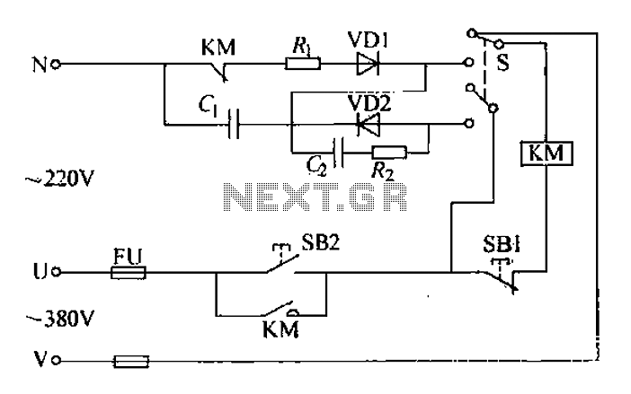
The AC contactor operates silently, demonstrating significant energy-saving effects, low noise, and a reduced operating temperature, which contributes to an extended lifespan. It is widely utilized in the production industry. When the SB2 button is pressed, the N-terminal receives...
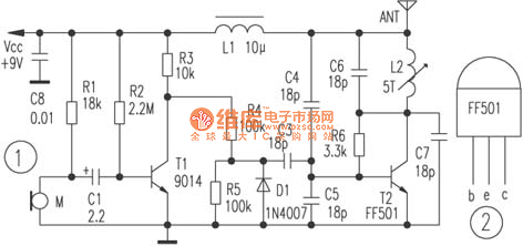
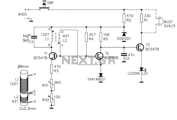
The circuit depicted utilizes a specialized launch tube T2 along with its associated components to create a high-frequency oscillator operating within the frequency range of 88 to 108 MHz. An electret microphone captures the audio signal, which is subsequently...
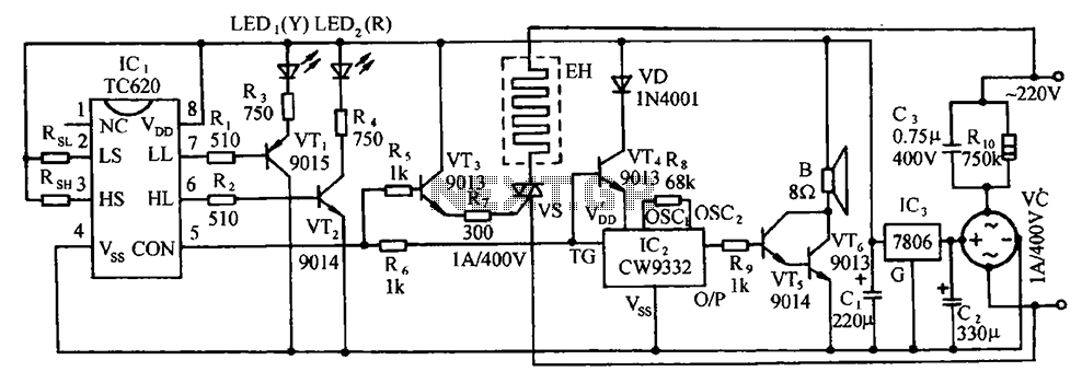
The circuit includes the TC620 temperature control circuit, the temperature indicator circuit, a thyristor-controlled heating circuit, a vocal music buck rectifier circuit, and the AC circuit. The TC620 temperature control circuit is designed to regulate temperature by monitoring the temperature...
The project demonstration has been successfully completed, with the only remaining task being the final project report due on June 15, which will be integrated with a conference paper. This update marks the last entry in the electronic notebook,...
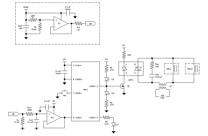
While discussing an all-linear automatic night light circuit, it was mentioned that an MCU-based Automatic Night Light Controller (ANLC) was being tested. The firmware has been tweaked since then. Recently, the sensor was installed outdoors and connected to control...

Sometimes referred to as the JFET µ-amp, this circuit offers a very low power, high gain amplification function. As the drain current decreases, the µ of a JFET increases, meaning that the lower the drain current, the greater the...