
555 jewelry small electronic circuit diagram
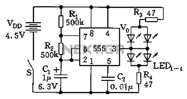
The described circuit utilizes the well-known 555 timer IC, which functions in an astable mode to produce a continuous square wave output. The output frequency is determined by the values of R1, R2, and C1. In this configuration, R1 and R2 are connected in series with the discharge pin and threshold pin of the 555 timer, while C1 is connected between the threshold pin and ground. The charging and discharging of C1 through R1 and R2 creates a repeating cycle of high and low output states, resulting in a flashing effect for the connected LEDs.
The choice of resistors R3 and R4 is crucial as they limit the current flowing through the LEDs, preventing damage due to excessive current. The selection of different colored LEDs allows for a variety of visual effects, as each LED may have different forward voltage requirements and luminosities. The circuit can be powered by a standard power supply, typically in the range of 5V to 15V, depending on the specifications of the 555 timer and the chosen LEDs.
To enhance the circuit's performance and reliability, it is advisable to use decoupling capacitors across the power supply pins of the 555 timer to filter out any noise that may affect the timing accuracy. Additionally, incorporating a potentiometer in place of R2 could allow for adjustable frequency settings, providing further versatility in the flashing rate of the LEDs. Overall, this circuit is an effective and straightforward implementation of a flashing LED display using a 555 timer, suitable for various applications in decorative lighting and signaling. Circuit as shown by 555 and the light emitting tube. 555 and R1, R2, C1 composition astable multivibrator, the oscillation frequency f 1.44/(R1 + 2R2) C1, the vibration frequen cy of about 2Hz, flashes twice per second. If LED1 ~ LED4 choose different colors of light-emitting diodes, add luster. R3, R4 current limiting resistor.
Related Circuits
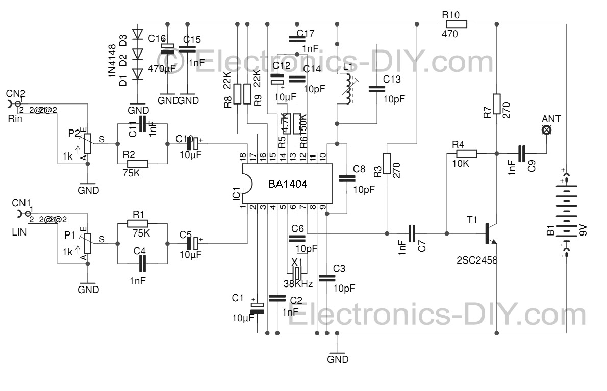
This Stereo FM Transmitter with BA1404 enables the creation of a mini stereo FM station, allowing for wireless audio broadcasting throughout a home. It provides a straightforward method for establishing an audio link without the need for complex wiring....
A 30W Class AB power amplifier circuit diagram utilizes a power transistor. To set up the amplifier, adjust the variable resistor R1 to its maximum value and R12 to zero. After completing this setup, activate the amplifier. Adjust R1...
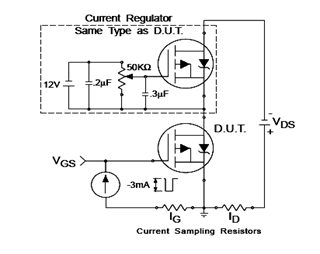
The IRF9540N Gate Charge Test Circuit is illustrated in the diagram below. The IRF9540N is recognized as a rectifier device that employs advanced processing techniques to attain an exceptionally low on-resistance per unit area, as stated in the datasheet....
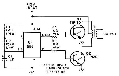
This low-power 25-watt power inverter circuit utilizes only nine electronic components. The inverter converts a DC input voltage ranging from 10V to 16V into a 60Hz, 115V square-wave power output, capable of powering AC electronic devices up to approximately...
Instructions for supervising landscaping projects recommended by satellite relay protection and automatic safety devices. This includes information on the general table for three remote programs related to petrochemical engineering construction, electrical transmission, and the intelligent implementation of community weak...

Inverters U1a and U1b are connected in a simple RC oscillator circuit. The frequency is determined by the values of R1, C1, C2, and the internal characteristics of the integrated circuit. As long as the circuit is oscillating, a...
Warning: include(partials/cookie-banner.php): Failed to open stream: Permission denied in /var/www/html/nextgr/view-circuit.php on line 713
Warning: include(): Failed opening 'partials/cookie-banner.php' for inclusion (include_path='.:/usr/share/php') in /var/www/html/nextgr/view-circuit.php on line 713