
555 mark space
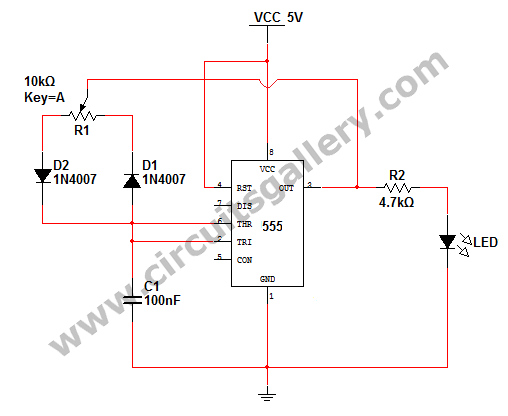
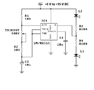
In an astable multivibrator configuration, the circuit operates continuously between its high and low states, generating a square wave output. The duty cycle, which defines the proportion of time the output is high compared to the total cycle time, is a critical parameter in applications such as pulse width modulation (PWM) and timing circuits. The addition of a potentiometer can allow for adjustments in the duty cycle, but the presence of a diode in parallel with resistor R2 limits the duty cycle to below 50%.
Incorporating a diode in parallel with resistor RB, with the cathode connected towards the timing capacitor, enhances the charging path of the capacitor. This design ensures that during the charging phase, current flows through resistor RA and the parallel diode, allowing the capacitor to charge more effectively. The inclusion of a second diode in series with RB, oriented with the cathode away from the timing capacitor, facilitates the discharge of the capacitor through RB and the discharge transistor. This dual-diode configuration broadens the operational duty cycle range significantly, permitting values from less than 5% to over 95%.
For optimal performance, it is crucial to select a minimum resistance value of 3kΩ for RB, which is essential to initiate oscillations reliably. In contrast, a simpler astable multivibrator circuit that omits the diode and utilizes the output at pin 3 tends to exhibit instability, as it is sensitive to variations in supply voltage, affecting both frequency and duty cycle. Therefore, while the simpler circuit may be appealing for its reduced component count, the enhanced stability and performance of the diode-inclusive design make it preferable for most applications.On astable multivibrators, the duty cycle is usually fixed unless there`s a potentiometer in place, but even still with a diode in parallel with R2, you will only get a duty cycle less than 50%. Also, to ask a question in a new thread, youcan click here. I`ve only been dealing with electronics for about 2 years now. The other people on this forum are much more helpful. it becomes necessary to insert a diode in parallel with RB, cathode toward the timing capacitor. Another diode is desirable, but not mandatory (this one in series with RB), cathode away from the timing capacitor. Now the charge path becomes RA, through the parallel diode into C. Discharge is through the series diode and RB to the discharge transistor. This scheme will afford a duty cycle range from less than 5% to greater than 95%. It should be noted that for reliable operation a minimum value of 3kW for RB is recommended to assure that oscillation begins.
That circuit is quite common. The circuit without a diode, but using the output at pin 3 is susceptible to changes in frequency and duty cycle with changes in voltage. It is a tiny bit simpler circuit than the conventional circuit with a diode, but I prefer not to use it because of its poor stability.
🔗 External reference
Related Circuits
This project is designed to assist in a basic course where students create a simple AVR/Arduino-based badge. It serves as a beginner's soldering project, resulting in a small object with blinking lights that can be worn around the neck...
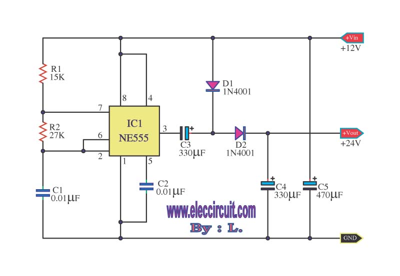
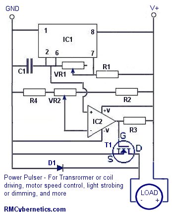
This is a simple voltage doubler circuit that converts 12V DC into 24V DC. It utilizes the popular NE555 timer IC along with a few additional components. The circuit can provide approximately 50mA of current, making it suitable for...
How to change the brightness of an LED. Are LED lights dimmable? Is it possible to adjust the brightness of LEDs? An LED is essentially a diode; when the forward voltage exceeds 0.7 volts, it begins to emit light,...
A 555 timer can be used to generate a square wave to produce a negative voltage relative to the negative battery terminal. When the timer output at pin 3 goes positive, the series 22 uF capacitor charges through the...
This is a simple LED flasher project that utilizes a common 555 timer integrated circuit (IC) for its operation. It is configured in astable mode, which means its output functions as a square wave oscillator. Two LEDs are connected...

There have described the involvement benefited LM3909 circuit, which is quite expensive. That's why I prefer to use a much cheaper known timer 555th. Involvement of the tree is a very simple scheme is to figure 2. It is...