
DSpace badge board build Instructions
Begin by soldering the resistors: R1, the 10K resistor at the top, serves as the reset pull-up resistor, while R2 to R6 are all 1K resistors used for limiting current to the LEDs, arranged for aesthetic alignment. Next, focus on the CPU. The chip has a dot on one corner, indicating pin 1, which corresponds to a matching dot on the board. The pin 1 side of the chip should be positioned at the top of the board, with a notch on that end facing up, adjacent to resistor R1. Carefully insert the pins into the board holes without applying excessive force; if necessary, gently bend the pins to the correct angle. After ensuring pin 1 is correctly positioned, flip the board and solder the CPU in place, taking care to use quick soldering motions to avoid heat damage.
Proceed to install the switches, ensuring the 'on' label on the switch aligns with the 'on' printed on the board. Next, install the resonator (the blue component with three in-line legs) into SV7, which serves as the oscillator generating the 10MHz system clock; orientation does not matter. Place C2, the 100nF disc ceramic decoupling capacitor, next to the resonator, which can also be inserted in either direction.
At the bottom right of the board, insert the five LEDs, ensuring correct orientation. Identify the anode and cathode of each LED by noting the flat side or the lead length; the shorter lead or the lead adjacent to the flat side corresponds to the negative side. Insert this lead into the hole marked with a flat side for each LED.
C1, the second decoupling capacitor, is electrolytic and polarized; the negative side is typically marked with a line of dashes, while the positive side is indicated with a '+' sign on the board. Ensure proper orientation when inserting this capacitor, with the negative side facing the CPU chip on the left side of the board.
Finally, solder the battery holder to the top of the board, paying attention to orientation to ensure the battery can be properly inserted. The scalloped side of the holder should face the right edge of the board, while the flat side should be centered. Verify that the holder is precisely centered and not touching the exposed round area on the circuit board (the negative terminal). This component is optional but is necessary if programming the board is desired.This project is intended to support a simple course in which a student builds a simple AVR/Arduino based badge - a beginner`s soldering project producing a simple object with blinky lights that can be hung around the neck from a lanyard or pinned to a jacket I usually start with the parts that stick the least above the board then work outwards - t his way when you place the board upside down to solder parts they stay in place more easily. The board hangs diagonally - however CAD systems don`t like that, so by convention the `top` of the board has the switches (see the picture below with the board oriented top up), the battery (the round circle) is on the `right` the `reset` switch on the `left` and the LEDs at the bottom right. The schematic for what we`re building is also available. And if you have a copy of the Eagle CAD program you can look at the layout as well (look in the downloads section) Solder in the resistors - R1 the 10K resistor at the top is the reset pullup resistor, R2-6 are all 1k and are the LED current limiting resistors - it looks prettier if they are all lined up the same way.
First the CPU - look at the chip, on the top one corner has a dot next to it - this is pin 1 - there is a matching dot on the board - the pin 1 end of the chip should be at the `top` side of the board. There is also a notch in this end of the chip, the notch should face up and be located right next to resistor R1.
Gently insert the pins into the holes on the board, don`t force them - chances are they are splayed slightly too far apart - place one side of the chip against your work bench and very gently bend all the pins on that side to the correct angle, then do the other side. Once the pins are in place check again that pin 1 is in the right place, turn the board over and gently solder the CPU in place.
This chip can be damaged by heat so use quick soldering motions. Now do the same with the switches - note that the word `on` is printed on the switch and should be on the same side (the `bottom`) as the `on` printed on the board. Do not copy the image above, I got it wrong. Install the resonator (blue thing with 3 in-line legs) in SV7, this is the oscillator that creates the 10MHz system clock - it doesn`t matter which way around it goes, install C2, the 100nF disc ceramic decoupling capacitor next to it, it too can go in either way around.
(your kit may contain two 100nF caps - if they are different sizes choose the one that fits the holes. ) At the bottom right of the board go the 5 LEDs - it DOES matter which way around they go. There are two standard ways to figure out which pin is which on an LED - either a flat side on the LED next to one of the leads or one lead is longer than the other (or both) - the shorter lead and the lead on the flat side are the same - in this case the picture above the holes for the LEDs show a flat side and one of the leads on your LED is shorter - push this lead into the hole on the flat side of each LED.
C1 is the second decoupling capacitor, it`s an electrolytic and is polarised - by convention the -ve side is usually marked with a line of `-` signs, also in a strangely bizarre convention we often mark the +ve side on a board with a `+` - go figure. Look at the mark on the cap and on the board - slide it in - the -ve side should be facing the CPU chip (`left` of the board).
Finally solder the battery holder to the top of the board - it does matter which way around you put it in as if you get it wrong you wont be able to slide the battery in. Have a look at the picture above, the scalloped side should face the `right` edge of the board, the flat side the centre of the board.
Look carefully underneath while you do this make sure that the holder is exactly centered and neither side is touching the exposed round area on the circuit board (the -ve terminal). This component is optional, it`s not required, but if you want to program the board 🔗 External reference
Related Circuits
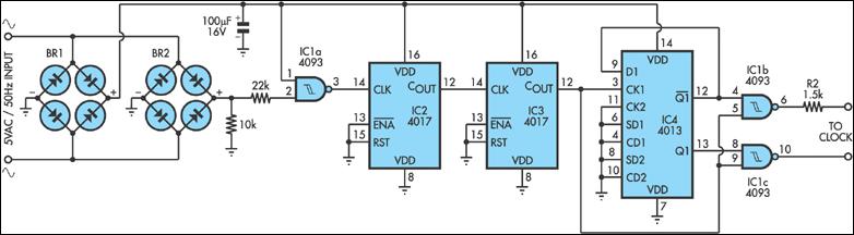
Quartz clocks have dominated timekeeping for the past 20 years but have a cumulative error that can become significant over time. While crystal frequency adjustments can correct some errors, regular resetting is often necessary. In contrast, mains-powered synchronous clocks...
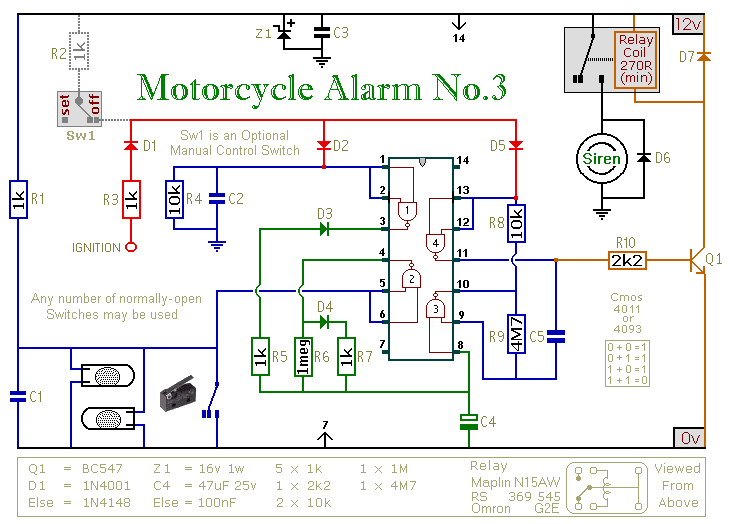
This circuit includes an intermittent siren output with an automatic reset feature. It can be manually operated using a key switch or a concealed switch, and it can also be configured to activate automatically when the ignition is turned...
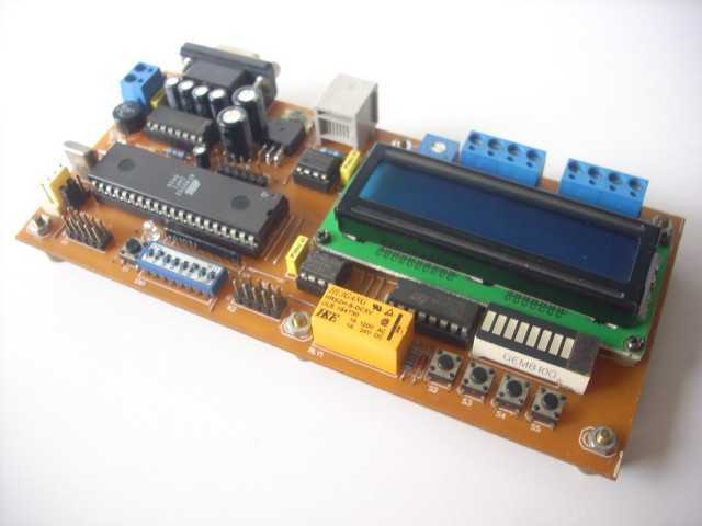
The hardware block is shown in Figure 1. The MCU is 89Sxx microcontroller. And the complete hardware schematic is shown in Figure 2. Port1 is used as data-bus for LCD (4-bit interface, PCB layout for 16x2 character with backlight),...
The circuit on this page is for a simple light detector circuit board that has 8 detectors that can be used with visible or infrared light systems. The detectors use LM339 voltage comparators as the active element. Phototransistors or...
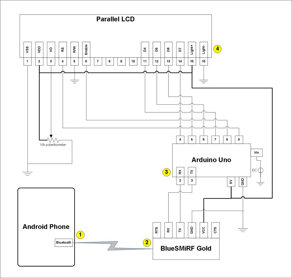
This project involves a modification of the Google Android sample app known as Bluetooth Chat, allowing users to type a message in the Android app and display that same message on an LCD connected to an Arduino Uno. The...
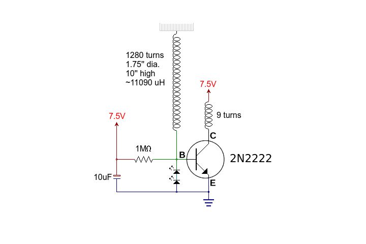
This circuit is straightforward. The accompanying graphics and images provide all necessary details. After gathering all materials, connect the transistor according to the provided schematic. The circuit in question is a basic transistor circuit that serves as an introductory project...