
555 Pulse Generator
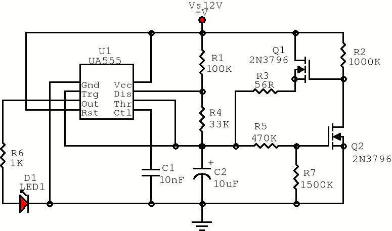
The described circuit utilizes a 555 timer in astable mode, which is known for generating a continuous square wave output. The addition of components to modify the behavior of the first pulse is essential for applications where pulse width uniformity is critical. The capacitor C2 plays a pivotal role in timing; its charging rate is influenced by the resistors R3 and the configuration of Q1 and Q2.
Transistor Q1 is responsible for facilitating the rapid charging of C2, while Q2 acts as a switch that controls the discharge path of the capacitor. The voltage divider formed by R5 and R7 is strategically placed to ensure that Q2 turns on at the correct voltage level, which is crucial for maintaining the desired pulse width. The choice of resistor values must consider the specific characteristics of Q2, particularly its gate-source threshold voltage, to ensure reliable operation under varying supply voltages.
In summary, this circuit modification effectively synchronizes the first pulse with subsequent pulses by leveraging the charging characteristics of C2 and the switching behavior of Q1 and Q2. Proper selection of component values is critical to achieving the desired performance, ensuring that the oscillator operates reliably in applications requiring precise timing sequences.The first positive pulse from a classic 555-based oscillator is always 1. 6 times longer than the following pulses. The difference is caused by the fact that only during the first cycle C2 starts charging up from 0 V. This is generally not a problem, but sometimes this first pulse just should be the same length as the rest - at least approximately.
The picture shows the oscillator and an addition to it (everything to the right from the Vs-Gnd axis) that can solve the problem. Immediately after switch-on, C2 is empty and the voltage on the gate of Q2 is low. Q2 is off and it makes C2 charge up very quickly through Q1 and R3 until it reaches just below Vs/3. Then Q2 turns on, Q1 turns off, and the classic circuit continues to charge and discharge C2 relatively slowly between 2Vs/3 and Vs/3.
As the voltage on C2 never again drops below Vs/3, Q2 now conducts all the time and Q1 is permanently off. The component values may be critical. For best results, the R5/R7 voltage divider should turn Q2 on when C2 is charged up to just a little below Vs/3.
This point is set by the R5/R7 ratio. But if the value of R5 is too high or if R7 is too small (depending on the supply voltage and the G-S threshold voltage of Q2), the oscillator may not work at all. The sum of R5 and R7 should be as high as possible in order to minimize the influence on the main part of the circuit after the first pulse.
🔗 External reference
Related Circuits
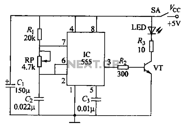
The circuit utilizes a 555 timer integrated circuit along with a transistor (VT) and several external components to create a multivibrator circuit. The charge and discharge time constants, Ti and T2, are defined, where Ti is approximately 0.7 times...
There are various methods to create pedal generators, utilizing different components such as bicycle parts or exercise bikes as a foundation. Each approach has its advantages and disadvantages, but for individuals who have not constructed one before and wish...
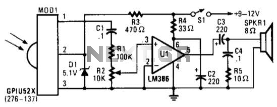
This circuit utilizes an infrared pulse-to-audio converter to assist in troubleshooting infrared remote controls, making it an effective tool for detecting infrared light sources. It employs a photo cell module (Radio Shack P/N 276-137) to detect IR radiation and...
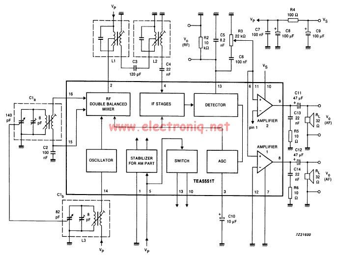
The TEA5551T monolithic integrated radio circuit can be utilized to design an AM radio receiver, intended for use as a portable radio receiver with headphones. The TEA5551T radio receiver circuit encompasses all necessary components for a complete AM receiver,...
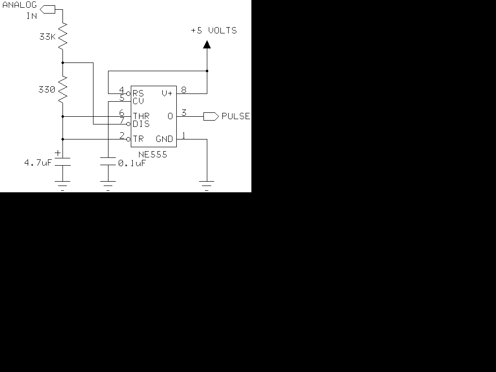
The 555 timer generates positive pulses. The pulse width is inversely proportional to the difference in voltage between the "ANALOG IN" voltage and the voltage across a 4.7 µF capacitor (approximately 2.5 volts). To calibrate this circuit, connect it...
One of the primary objectives was to convert a generator into a motor using an Arduino. The process of transforming a simple generator into a motor proved to be particularly challenging with a three-phase generator, necessitating the creation of...
Warning: include(partials/cookie-banner.php): Failed to open stream: Permission denied in /var/www/html/nextgr/view-circuit.php on line 713
Warning: include(): Failed opening 'partials/cookie-banner.php' for inclusion (include_path='.:/usr/share/php') in /var/www/html/nextgr/view-circuit.php on line 713