
555 Sawtooth Oscillator
The 555 Sawtooth Oscillator is a versatile circuit that utilizes the 555 timer IC to generate a sawtooth waveform, which is characterized by a linear rise followed by a rapid drop. This type of waveform is commonly used in applications such as audio synthesis, signal modulation, and as a timing reference in various electronic circuits.
The circuit typically operates in astable mode, where the 555 timer continuously switches between its high and low states, producing a periodic output. Key components in this configuration include resistors, capacitors, and the 555 timer itself. The frequency and duty cycle of the sawtooth waveform can be adjusted by changing the values of these passive components.
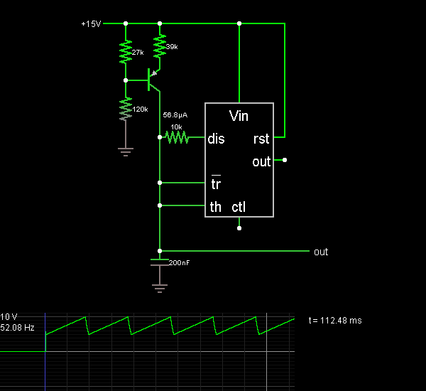
In the standard configuration, a resistor (R1) is connected between the discharge pin (pin 7) and the supply voltage (Vcc). A second resistor (R2) connects the discharge pin to the threshold pin (pin 6). A capacitor (C1) is connected from the threshold pin to ground. The output is taken from the output pin (pin 3) of the 555 timer.
During operation, the capacitor charges through both resistors, causing the voltage across it to rise linearly. Once this voltage reaches approximately two-thirds of the supply voltage, the 555 timer resets, discharging the capacitor rapidly and causing the output to drop. This cycle repeats, generating the sawtooth waveform.
The frequency of oscillation can be calculated using the formula:
\[ f = \frac{1.44}{(R1 + 2R2) \times C1} \]
Where:
- \( f \) is the frequency in hertz (Hz),
- \( R1 \) and \( R2 \) are the resistances in ohms (Ω),
- \( C1 \) is the capacitance in farads (F).
The duty cycle, which defines the proportion of time the output is high versus low, can also be adjusted by varying the resistor values. A lower R2 value results in a higher duty cycle, while a higher value decreases it.
This circuit can be simulated using various electronic circuit simulators, allowing users to visualize the waveform and make adjustments to component values in real-time. This feature aids in understanding the behavior of the sawtooth oscillator and its applications in different electronic systems.This is the 555 Sawtooth Oscillator circuit diagram with the detailed explanation of its working principles. The electronic circuit simulator helps you to design the 555 Sawtooth Oscillator circuit and to simulate it online for better understanding..
🔗 External reference
Related Circuits
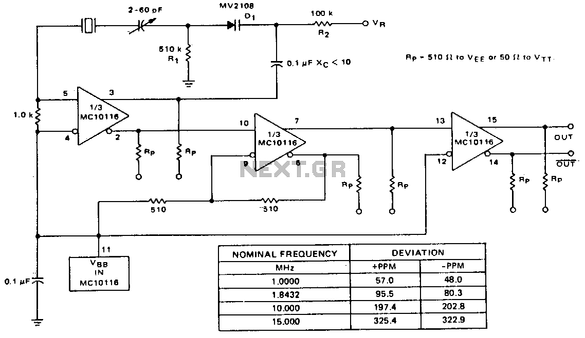
A voltage-variable capacitance tuning diode is connected in series with the crystal feedback path. Adjusting the voltage on the variable resistor (VR) changes the capacitance of the tuning diode, which in turn tunes the oscillator. The 510 kΩ resistor...
The circuit below illustrates generating a single positive pulse which is delayed relative to the trigger input time. The circuit is similar to the one above but employs two stages so that both the pulse width and delay can...
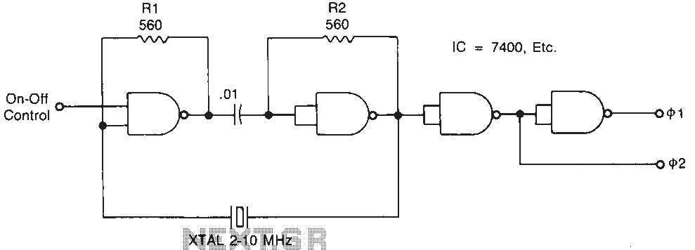
Temperature-stable resistors R1 and R2 are used in NAND gate configurations, ensuring that the switches operate in the linear region. Capacitor C1 functions as a DC component at the operating frequencies. Additionally, the impedance must remain below 0.1 ohm....

The controller circuit illustrated in Figure 15-24 consists of a switch-type Hall integrated circuit DN838 and an astable multivibrator, which is based on the 555 timer IC. This circuit is suitable for various applications, including automatic door opening, delay...

Figure 15-22 illustrates a doorbell system that consists of a monostable timing circuit, a password switch, a NAND gate circuit, and a sound output circuit. The operation of the circuit is designed such that when the password switch is...

This design outlines a fire alarm circuit that utilizes a light-dependent resistor (LDR) and a lamp to detect fire. The alarm is activated by sensing the smoke produced during a fire. When smoke is present, it obstructs light from...