
555 tester circuit
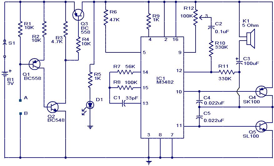
The 555 tester circuit is designed to verify the operational status of the 555 timer integrated circuit (IC). Upon application of power, the circuit initiates a blinking LED sequence, serving as a visual indicator of the 555 IC's functionality.
The schematic typically includes a 555 timer configured in astable mode, which allows it to oscillate between high and low states, thereby producing a square wave output. The frequency of this oscillation can be adjusted using external resistors and capacitors connected to pins 6 (threshold) and 2 (trigger) of the 555 timer.
Power is supplied to the circuit through a suitable voltage source, often within the range of 5V to 15V, depending on the specifications of the 555 timer being used. The output from pin 3 of the 555 timer is connected to the anode of the LED, while the cathode is connected to ground through a current-limiting resistor. This resistor prevents excessive current from flowing through the LED, ensuring its longevity.
In addition to the basic components, a capacitor may be included between pins 6 and 2 to stabilize the timing interval and enhance performance. The values of the resistors and capacitor determine the blinking rate of the LED, allowing customization based on the user's requirements.
This circuit serves not only as a functional tester for the 555 timer but also as an educational tool for understanding the principles of timing circuits and LED operation. It demonstrates key electronic concepts such as oscillation, timing intervals, and the relationship between frequency and component values.A project of a 555 tester circuit, the circuit will start blinking LEDs when power is applied which will indicate that the IC is working correctly.. 🔗 External reference
Related Circuits
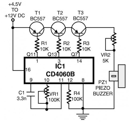
The circuit generates pulses of 1.25 Hz from pin 1 and 20 Hz from pin 14. The three output pins of IC1 are connected to the base terminals of transistors T1, T2, and T3 through resistors R1, R2, and...
This project involves a 555 buzzer circuit utilizing the NE555 timer IC, which comes in an 8-pin DIP package and performs a wide variety of functions in electronic circuits. The circuit described will produce a buzzer sound when a...
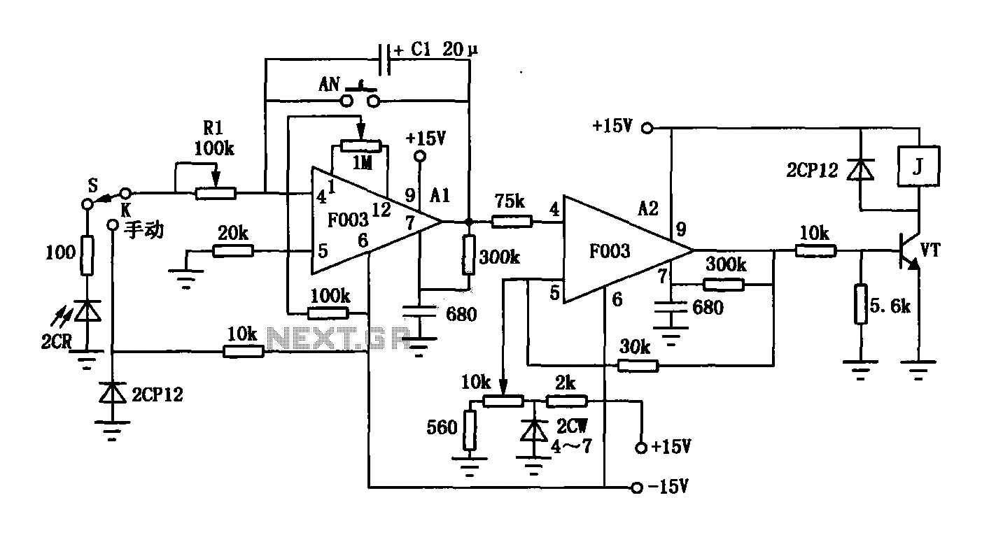
The F003 circuit is a versatile photographic component that functions as an operational amplifier amplifying automatic timer circuit. The operational amplifier A1 serves as an integrator, while operational amplifier A2 is configured as a comparator. A 2CR silicon photocell...
The objective is to enhance information transmission through the distribution of articles. Please contact us via email at [email protected] within 15 days if there are any issues related to article content, copyright, or other concerns. Prompt deletion will occur...
This is a hobby circuit designed as a water or liquid sensor. Its primary function is to activate an alarm when water or liquid is detected at its probes. The water sensor circuit typically consists of a few essential components,...
The closed-loop system consists of longitudinal and transverse components. The circuit operates as follows: a control circuit from the stepping motor CNC system issues a command, which the receiver detects. This signal is processed through a phase-sensitive rectifier to...